


DV425TR DIRECT VENT ROOM HEATER
02/01 Page 33 250-5533
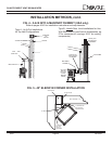
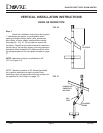
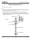
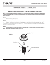
NOTE: Maximum number of 90° elbows permitted for a vertical installation is four, provided the termination
falls within the shaded area shown in vent graph on page 33. See also Figure 12 below, within the 4, 90’s
configuration, the maximum allowable pipe length on the horizontal runs is 1’, the minimum allowable pipe
length on vertical runs is 1’. ADDITIONAL RESTRICTION: This installation may not have two horizontal
sections connected by 90° elbows.
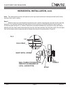
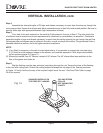
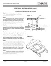
Step 2.
Set the gas stove in its desired location. Drop a plumb bob down from the ceiling to the position of the
stove flue exit, and mark the location where the vent will penetrate the ceiling. Drill a small hole at this
point. Next, drop a plumb bob from the roof to the hole previously drilled in the ceiling, and mark the spot
where the vent will penetrate the roof. Determine if ceiling joists, roof rafters, or other framing will obstruct
the venting system. You may wish to relocate the stove, or to offset, as shown in Figure 11, to avoid cutting
loadbearing members.
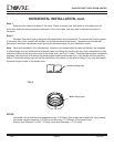
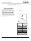
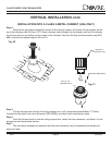
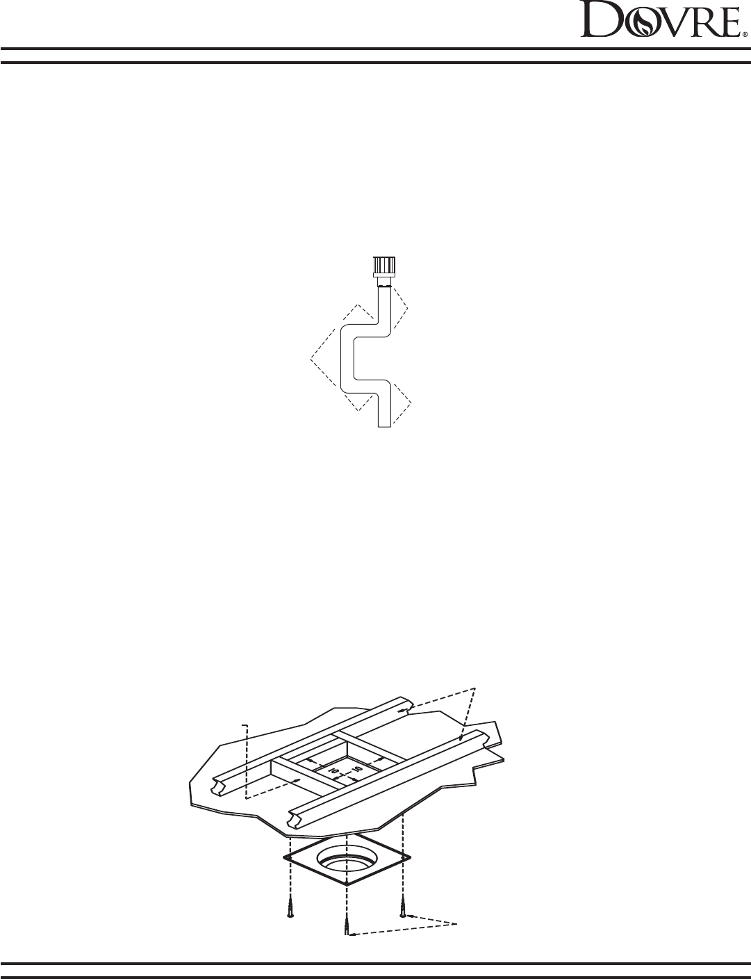
Step 3.
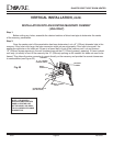
To install the round support box/wall thimble in a flat ceiling, cut a 10" (254mm) square hole in the
ceiling, centered on the hole drilled in Step2. Frame the hole as shown in Figure 13.
FIG. 12
VERTICAL INSTALLATION INSTRUCTIONS, cont.
2'
1'
2'
1'
1'
FIG. 13
FRAMING
1 - 1/2" LONG
WOOD SCREWS
CEILING JOISTS