


DV425TR DIRECT VENT ROOM HEATER
02/01 Page 17 250-5533
REMOTE CONTROL
A remote control or a wall switch may be wired to the thermostat
terminals. Contact your Dealer for details.
Manual Thermostat #812-2880
Anticipator Setting 1.2
Programmable Thermostat #811-0520
Recommended Maximum Lead Length (2 wire) when using wall
thermostat/switch:
Wire Size Maximum Length
16 gauge 65 Feet
18 gauge 40 feet
20 gauge 25 feet
22 gauge 18 feet
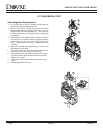
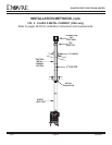
THERMOSTAT INSTALLATION
A thermostat may be installed to regulate the 425TR. It is
important to use a thermostat designed for millivolt operation
Do not connect the heater to a thermostat serving any other
appliance. Bedroom installation in Canada requires this heater to
be connected to a thermostat.
Connect the thermostat wires to the outside valve terminals
labeled "TH" and "TPTH". Turn the manual switch on the control
panel to "OFF".
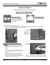
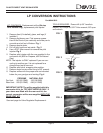
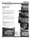
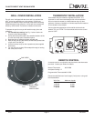
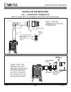
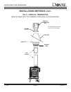
GRILL COVER INSTALLATION
Top grill cover is shipped with the stove and is an optional use
item. It may be used with rear or top venting. Primarily its
purpose is to hide the interior of the top of the stove from being
viewed through the top grill piece. Its use will also increase the
efficiency of the blower, if a blower is installed on the stove.
To prepare the part for use you will need tin snips, pliers and
a hammer.
1, For use with top venting: See Fig. 1 below. Use the tin
snips to cut the straight edges.
2. Gently bend the piece until the two attached sections of the
circular area snap apart. Discard this piece.
3. Bend the tabs up towards the black painted side.
4. With the top grill lying face down, set the black painted side
of grill cover onto the grill.
5. Use the hammer to tap on the 4 speed nuts (also supplied
with stove.)
6. For use with rear venting: Follow steps 3 through 5, leaving
the cover piece in tact.
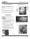
FIG. 1
SNIP HERE
BEND 7 TABS
TOWARDS
PAINTED SIDE