


DV425TR DIRECT VENT ROOM HEATER
02/01 Page 27 250-5533
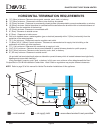
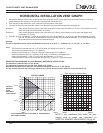
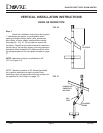
1. Measure the distance from the top of stove to the center of the 90° elbow. On the graph below, draw a horizontal line from that
measurement on the vertical axis across until it intersects with the slanted line.
2. From the point of this intersection, draw a vertical line to the bottom of the graph.
3. The point at which this line meets the bottom line of the graph is the maximum length of the horizontal run.
Example 1: If the vertical dimension from the top of the stove to the center of the 90° elbow is 7’ (2.13m), the horizontal run to the
outer wall flange must not exceed 9’ 9” (2.97m).
Example 2: If the vertical dimension from the top of the stove is 21’ (6.4m), the horizontal run to the outer wall flange must
not exceed 7’ 3” (2.21m).
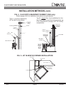
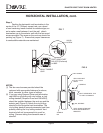
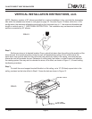
4. Each 90° elbow is equivalent to 3' of vent pipe and each 45° elbow is equivalent to 1' of vent pipe, and must subtracted from vent
pipe run. A single vertical to horizontal 90° elbow is already calculated into the allowable 15' run. Each additional 90°
elbow reduces the maximum horizontal distance by 3'.
Example:
The use of [3] elbows would reduce the allowable horizontal run to 9' (3 - 1 = 2 elbows x 3' = 6'; 15' max. - 6' = 9' max.)
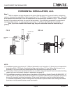
Notes:
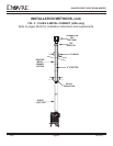
The maximum horizontal vent run is 15’ (4.57m) when the vertical vent rise is 10’ (3.05m).
The minimum horizontal vent run is 12” (305mm).
Minimum wall thickness is 4” (102mm). Maximum wall thickness is 20” (508mm).
Horizontal sections require a 1/4” (6mm) rise for every 12” (305mm) of horizontal travel.
Exterior Vent Diameter = 6 5/8” (177mm); Inner Vent Diameter = 4” (101mm)
Horizontal sections require noncombustible support every 3’ (914mm) , e.g. plumbing tape.
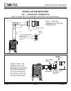
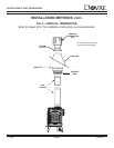
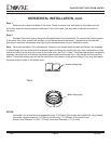
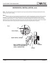
EXCEPTION FOR REAR VENT KIT (Part #844-8920), HORIZONTAL INSTALLATION:
The maximum horizontal vent run is 2' (61cm)
The maximum horizontal vent run with a 45° elbow is 14" (35cm)
No external minimum rise is required. The minimum horizontal vent run is 11-5/8" (29cm).
For any vertical rise when rear venting, a minimum of 2' (61cm) vertical must be used prior to any horizontal run.
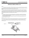
NOTE: If your installation falls within the grey-
shaded area on graph, see information on
VERTICAL DAMPER ADJUSTMENT ON pg. 48.
HORIZONTAL INSTALLATION VENT GRAPH
TOTAL HORIZONTAL RUN TO OUTSIDE OF EXTERIOR WALL
(EXCLUDING ELBOWS)
VERTICAL
DISTANCE
FROM
APPLIANCE
TO 90° ELBOW
EX. 2
EX. 1
11" 2' 4' 6' 8' 10' 12' 14'
30'
28'
26'
24'
22'
20'
18'
16'
14'
12'
10'
8'
6'
4'
2'
0'
(MAX)
(MIN)
TOP VENT GRAPH
2' 4' 6' 8' 10'
30'
28'
26'
24'
22'
20'
18'
16'
14'
12'
10'
8'
6'
4'
2'
0'
(MAX)
(MIN)
Rear Venting w/ Vertical Rise