


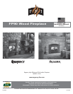
FPI FP90 Wood Fireplace 9
INSTALLATION
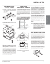
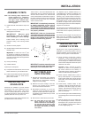
50-3/4"
(1289mm)
44"
(1118mm)
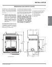
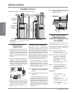
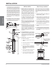
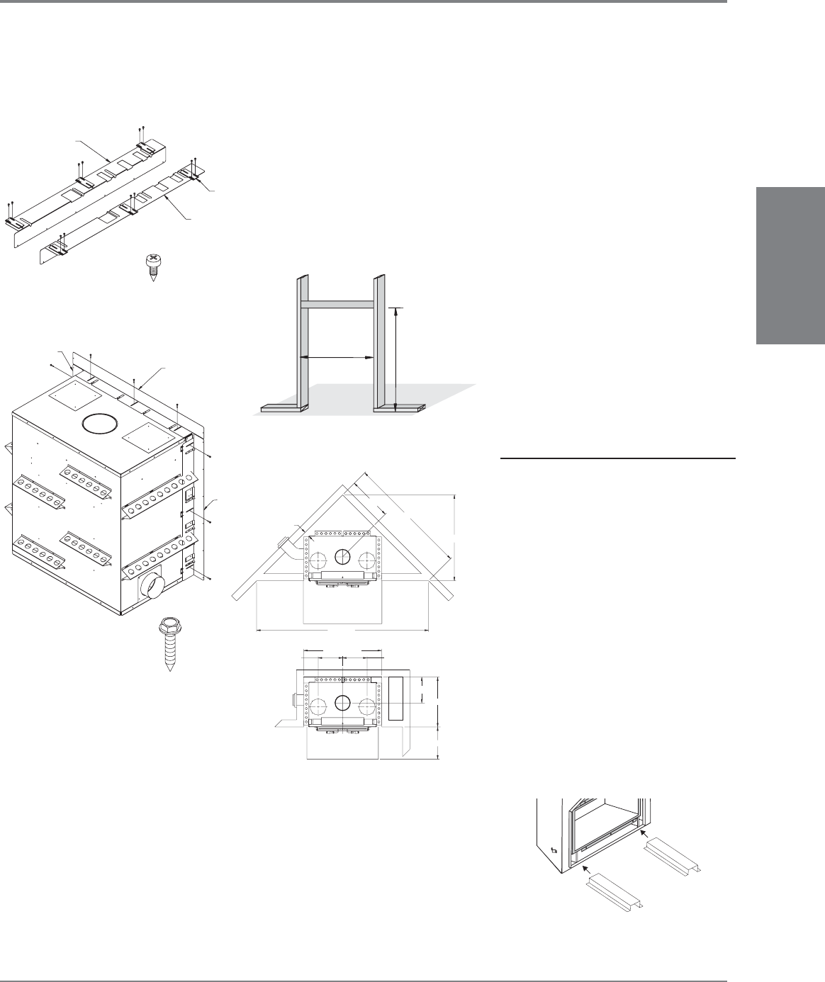
INSTALLATION OF
NAILING STRIPS
1) Assemble 3 Nailing Strip Spacer Plates
to the left and the right Nailing Strips as
shown below.
Left Nailing Strip
Nailing
Space
r
Right Nailing
Strip
x 12
Right Nailing Strip
Top Nailing
Strip
Left
Nailing
Strip
x 9
2) Mount Nailing Strips left, right and top to the
positions indicated below.
NOTE:
Nailing Strips are adjustable to allow for correct
offset from the front of the fi replace for your
current application.
There are two adjustments to allow for maximum
offset (1" , 25mm recessed from front of fi replace
or 1.25", 32mm extending past front of fi replace).
The Nailing Strip Spacers can be adjusted by
loosening the two screws securing them to the
Nailing Strips. The Nailing Strips can also be
moved forward and back by adjusting the screws
that mount them to the fi replace.
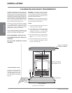
FIREPLACE
ENCLOSURE FRAMING
As per the diagram, the framing of the main
enclosure should not infringe on the area above
the fi replace to the ceiling level. The rear and
side walls as well as the face above the fi replace
must not extend into the area above the unit.
The only structure allowed above the unit is on
the stand-offs at the front of the unit supporting
the header.
The enclosure walls can be framed using any
suitable material (2x4 - 2x6 studs, plywood,
gyproc, etc.), Normally, framing will be set
back to allow Non-Combustible Material to
be fl ush with the front of the fi replace.
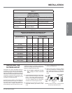
Framing Specifi cations
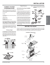
INSTALLATION
There is framing only on the front of the unit.
When framing in the header (directly above
the fi replace) DO NOT bring any combustible
material lower than the top of the stand-offs.
Framing header may be positioned on end
directly on top of the front fi replace stand-offs.
Be sure to seal the space between the fi replace
and the enclosure above and on either side of
the unit with Wonderboard, Durock or other
similar non-combustible sheeting to prevent hot
air from entering the enclosure.
CAUTION: ONLY NON-COMBUSTIBLE
MATERIAL LIKE EXPANDED METAL
OR CONCRETE BOARDS SUCH AS
WONDERBOARD AND DUROCK,
ETC. MAY BE USED IN THE SPACE
BETWEEN THE UNIT AND THE
FRAMING IN FRONT OF THE UNIT
ONLY.
Note: If the fi replace is being cantilevered
through an outside wall, the entire
enclosure (floor, wall and false
ceiling) up to the fi rst ceiling level
must be completely insulated and
vapor sealed and sheathed, to avoid
transfer of cold air through the
fi replace when not in use.
Building Structures Cannot Encroach
on Chase
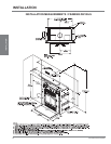
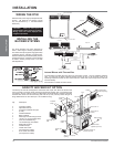
UNIT BASE STAND-OFFS
To accommodate varying thicknesses and
fi nishes of hearth materials, we have increased
the overall height of the appliance by a further 1
1/8”. This increase is added with the inclusion of
two stand-offs at the bottom of the unit, below the
outer box, taking the overall height of the framing
dimensions from 50-3/4” up to 51-7/8”.
In the event that you should choose to use thinner
materials to fi nish the hearth, you can omit the
stand-offs provided for raising the unit. However,
we recommend that you leave the framing
dimensions as they are in the manual and alter
only the facing requirement by reducing it by the
same distance that you have lowered the unit.
Insert the 2 unit base stand-offs underneath the
unit as shown in the diagram below. Space the
stand-offs centrally, approximately 2 or 2-1/2 feet
apart. Ensure that the unit is not unstable.
3” [76mm]
24½” [624mm]
68” [1729mm]
48½” [1222mm]
8
96¼” [2445mm]
13¾” [348mm]
44” [1118mm] CHASE
13¾” [348mm]
14¾” [370mm]
8
5
28” [710mm]
18” [457mm]