


FPI FP90 Wood Fireplace 15
INSTALLATION
INSTALLATION
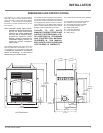
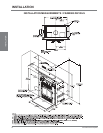
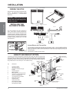
INSTALLING THE
OUTSIDE AIR KIT
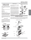
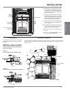
Combustion air is fed to the fi rebox through a
connection on the rear lower left side of the unit.
A free fl owing supply of air must be available to
this opening at all times. Combustion air may be
taken from inside the building if the local building
code allows, but performance may suffer. Also,
it must go through the 6" (152mm) duct to the
connection on the left hand side.
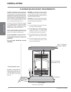
Air drawn from the interior of the building will
affect the performance of gas or oil furnaces,
and exhaust fans and fan driven appliances.
This may cause a negative pressure in the
house allowing smoke to back into the home.
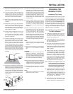
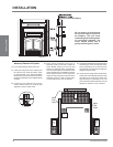
Outside Air Inlet must be 6 ft. (152mm) below
the chimney termination point
Insulated Metal
6” Duct
Exterior
Wall
Outside
Metal
Vent
Side Connectio
n
Unit
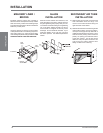
The preferred source of combustion air is from
outside the building. If possible, install the kit
on the wind loading side of the building not the
leeward or (negative pressure) side.
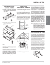
Note: Do not obtain combustion air from
attic, garage or other enclosed
space.
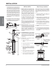
1) Put the supplied insulated air duct to a nearby
exterior wall. Maximum length of duct is 20ft
(6.1m). Duct length should be kept to a
minimum and as straight as possible. Note:
4 ft. only is supplied with unit. Termination
should be in an area with good air fl ow.
2) Ensure that your air source is not close to
automobile exhaust, gas meters or other
vents.
3) Cut a 7" (178mm) hole through the wall and
mount the outside air kit.
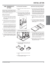
4) Attach the two ends of the duct (making
sure not to damage the insulating cover)
after installing the fl ange on the fi replace
side. Duct must be secured by screws or
clamp.
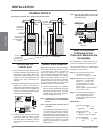
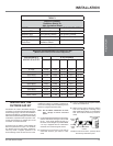
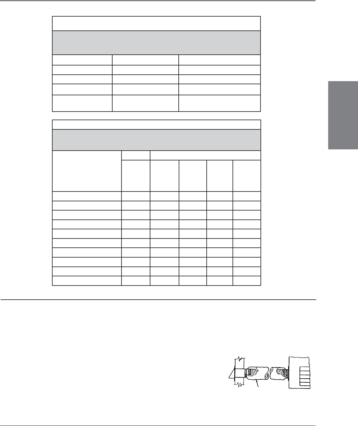
TABLE 1
Required Firestop,
Radiation Shield, Or
Attic Insulation Shield
MODEL 1st FLOOR 2nd FLOOR INTO ATTIC
Superior TF8 Joist Shield Firestop Attic Shield Firestop
Majestic SK8 Joist Shield Firestop Attic Shield Firestop
Security FTF8 Joist Shield Firestop Attic Shield Firestop
Simpson DuraVent
Dura-Plus
Intermediate Joist/
Radiation Shield
Attic Radiation Shield
TABLE 2
Minimum Recommended Flue Height In Feet
(Measured from the top of the solid fuel appliance)
ELEVATION (FT)
ABOVE SEA LEVEL
# OF ELBOWS
0
2 x 15
o
4 x 15
o
2 x 30
o
4 x 30
o
0-1000 12.00 13.00 14.00 15.0 18.00
1000-2000 12.48 13.52 14.56 15.6 18.72
2000-3000 12.96 14.04 15.12 16.2 19.44
3000-4000 13.44 14.56 15.68 16.8 20.16
4000-5000 13.92 15.08 16.24 17.4 20.88
5000-6000 14.40 15.60 16.80 18.0 21.60
6000-7000 14.88 16.12 17.36 18.6 22.32
7000-8000 15.36 16.64 17.92 19.2 23.04
8000-9000 15.84 17.16 18.48 19.8 23.76
9000-10000 16.32 17.68 19.04 20.4 24.48