


FPI FP90 Wood Fireplace 13
INSTALLATION
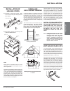
There is also 1" unit base standoffs that are
supplied with the unit. These are optional and
are to be used to raise the unit. The thickness
of the fi nished hearth will dictate the height of
the stove. Please be careful to ensure that the
bottom louver will open when unit is installed
with the fi nished hearth.
IMPORTANT: It is absolutely necessary
to attach stand-offs to the unit to
avoid combustion problems. Serious
overheating of combustible framing and
possible fi re may result if stand-offs are
not properly installed.
IMPORTANT: Under no circumstances
can the fi replace top or side spacers be
removed or modifi ed. Do not notch the
header to be installed closer than the
fi replace outside facing spacers.
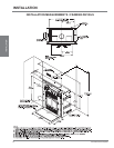
The fi replace may be installed directly on a
combustible fl oor or raised on a platform of an
appropriate height. Do not place fi replace on
carpeting, vinyl or other soft fl oor coverings. It
may, however, be placed on fl at wood, plywood,
particle board or other hard surfaces. Be sure
the fi replace rests on a solid continuous fl oor
or platform for support and to prevent cold air
from entering the room from under the fi replace,
if against an outside wall.
The fi replace may be positioned and then the
framing built around it, or the framing may be
constructed and the fi replace positioned into
the opening.
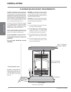
The minimum ceiling height is 7ft (2m) from the
base of the unit. A suitable non-combustible
hearth pad is mandatory in all installations. See
Framing Details section.
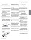
INSTALLING THE
CHIMNEY SYSTEM
Following are a set of general guidelines for
installation of the chimney system. The more
detailed installation manual supplied with the
specifi c chimney system must be followed.
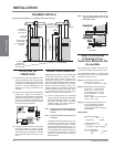
1) Using standard construction framing
techniques, construct the opening for the
chimney route up through the ceiling(s) and
roof or through an outside chase. Framing
must maintain adequate minimum air space
clearance at all times.
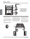
CAUTION: Allow a minimum 2" (51mm)
chimney air space or as specified by
the owner's manual for the chimney, to
combustible framing members throughout
vertical or offset chimney installation.
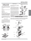
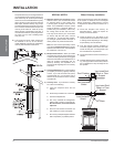
2) Attach fi replace adaptor/anchor plate to
the top of the fi replace. It is important that
a tight seal be made with this part and the
unit’s collar. This must be purchased with
the fi replace.
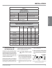
3) Install fi restop, radiation shield, or attic
insulation shield as required at each fl oor
penetration. See Table 1 (page 15). Check
chimney manufacturer's framing opening
sizes to allow for correct clearances. All
parts must be listed.
4) The roof fl ashing should be installed making
sure that alignment is correct with openings
below.
5) Chimney lengths may now be added until
the required height is reached. A minimum
fl ue height of 12ft. (4m) from the top of the
unit is mandatory. Please refer to Table 2
for Flue Heights (page 15).
INSTALLATION
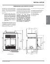
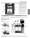
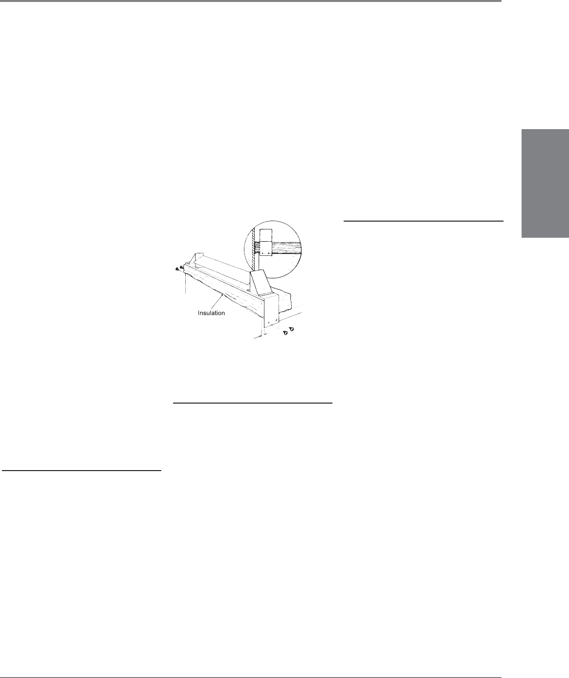
INSTALLING THE
STAND-OFFS
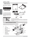
Stand-offs are installed to provide reduced
temperatures and proper clearances for the
safe installation of your product. They consist
of four 3" (76mm) stand-offs on the back, two
3" (76mm) stand-offs on each side and one 8"
(203mm) stand-off on the top of the unit.
Attach these stand-offs where indicated in the
pre-drilled holes on the unit body.
IMPORTANT: Insulation extends forward
to seal against the back of the fi replace
masonry or non-combustible face.
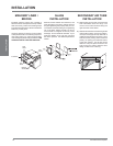
SET FIREPLACE
INTO POSITION
1) Estimate the total weight of the fi replace
system and surround materials such as
brick, stone, etc., to be installed. Shipping
weight is 612 lbs (278kg).
2) Measure the square footage of the fl oor
space to be occupied by the system,
surrounds and hearth extensions.
3) Note the fl oor construction, i.e. 2 x 10’s, (51
x 250 mm), single or double joists, type and
thickness of fl oor boards and consult your
local building code to determine if you need
additional support.
4) Remove door, fi rebox bricks, louvers etc.
Note: Set aside Gold louvers away from
harsh chemicals and away from
abrasive materials to avoid damage,
e.g. muriatic acid for masonry wash
will strip the gold plate. Firebricks
are fragile and should be handled
with caution.
ASSEMBLY STEPS
Note: The following steps represent the
normal sequence of installation.
Each installation is unique, however,
and might require different steps.
Each step is dealt with in detail in the
following pages.
1) Install stand-offs and insulation strip to the
unit.
2) Complete framing and installation of the
nailing strips for the FP90.
IMPORTANT: Remove gold
accessories such as louvers
while installing to avoid marking.
Position fi rebox prior to framing or into
prepared framing. See Framing Details
section.
3) Install the Chimney System.
4) Install Outside Combustion Air Kit and Chase
Ventilation Grill.
IMPORTANT: A chase vent of 30 in
2
(194
cm
2
) MUST be installed in all applications,
otherwise serious overheating of the chase
may result. Use the chase vent supplied with
the FP90 unit only.
5) Hook-up the Wiring.
6) Install the Blower.
7) Gravity Air Feed Option.
8) Complete fi nish wall material, surround and
hearth extension to your individual taste.
9) Position vermiculite liner / bricks and ceramic
fi ber insulation in the unit. Attach louvers,
glass, doors, handles.