


FPI FP90 Wood Fireplace10
INSTALLATION
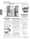
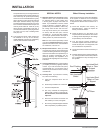
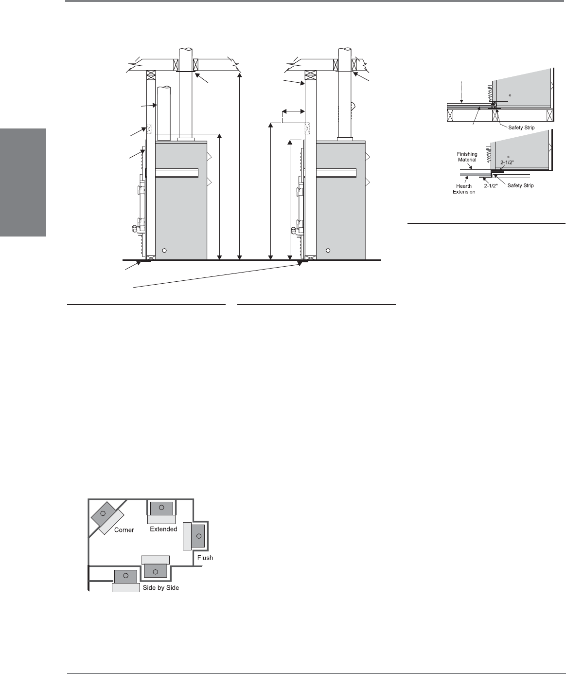
Fire Stop
FireStop
Straightrun
for 8"(203mm)
Hot Air Duct
Unit projects
out flush with
non-combustible
material
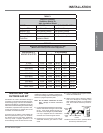
2 x 4 Framing
2 x 6 Framing
10"
2x6
Wall with a
2x4
Header
Stud
84"
(2137mm)
50-3/4"
(1289mm)
55-3/4"
(1416mm)
42-5/8"
(1083mm)
(254mm)
2 x 4
Stud Wall
5"(127mm)
wide sheet
metal strip under
unit and hearth
INSTALLATION
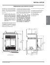
FRAMING DETAILS
LOCATION OF
FIREPLACE
1) Carefully select the proper location for heat
circulation, aesthetics, chimney obstructions
and clearance to side wall(s). With proper
pre-planning, a slight adjustment of a few
inches can save considerable time and
expense later during construction and
assembly.
2) Carefully consider the position of the fi replace
opening with respect to the location of
adjacent or nearby stairwells, bath or kitchen
exhaust fans and/or return air registers for
forced air furnaces/air conditioners that
could cause a smoking fi replace condition
if the house is tightly insulated.
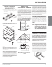
3) Fireplace must be anchored to the framing
to prevent movement or rocking; use the
nailing strips which have been supplied.
The nailing strips are installed to the side
of the unit and to the front side of the 2 x 4
or 2 x 6.
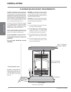
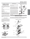
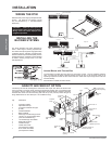
1) Insert the metal safety strip, packaged
with the fi replace beneath the fi replace as
illustrated in Diagram 1 below. The safety
strip should be tacked down to prevent
possible shifting and should overlap for
continual coverage of the fl oor.
Note: A safety strip is not required when the
fi replace rests on a non-combustible
surface.
Note: Install the hearth extension only as
illustrated.
The safety strip should extend 2 in. (51 mm)
in front and on the sides of the fi replace.
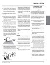
In the event a wooden support is used to
elevate the fi replace above the fl oor, a “Z”
type safety strip should be fabricated from
20 gauge galvanized sheet steel and used
to protect the front surface of the wood
support as well as the fl oor beneath the
hearth extension.
FINISHING MATERIAL
FINISHING MATERIAL
NON-COMBUSTIBLE
NON-COMBUSTIBLE
1/2"(13mm) THICK
1/2"(13mm) THICK
HEARTH EXTENTION
HEARTH EXTENTION
(64mm)
(64mm)
Diagram 1
Note: The “Z” type safety strip is not
supplied by Regency and must be
fabricated locally.
The proposed alternative is 4” (102mm) brick
with a C-factor of 1.25 over 1/8” (3mm) mineral
board with a k-factor of 0.29.
Step (a): Use formula above to convert
specifi cation to R-value.
R = 1/k x T = 1/0.84 x .75 = 0.893.
Step (b): Calculate R of proposed system.
4” brick of C = 1.25, therefore
Rbrick = 1/C = 1/1.25 = 0.80
1/8” mineral board of k = 0.29,
therefore Rmin.bd. = 1/0.29 x
0.125 = 0.431
Total R = Rbrick + Rmineral board
= 0.8 + 0.431 = 1.231.
Step (c): Compare proposed system R of
1.231 to specifi ed R of 0.893.
Since proposed system R is
greater than required, the system
is acceptable.
DEFINITIONS
Thermal Conductance:
C = Btu = W
(hr)(ft2)(oF) (m2))(k)
Thermal Conductivity:
k =(Btu)(inch) = W = Btu
(hr)(ft3)(oF) (m)(k) (hr)(ft)(oF)
Thermal Resistance:
R = (ft2)(hr)(oF) = (m2)(k)
Btu W
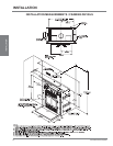
Note: Ducting is tested at 1 in. (25mm) clearance to framing.
HEARTH EXTENSION
NOTE: Hearth must have 1/2" (13mm) Millboard
under fi nish material with minimum "k" factor
of 0.84. When unit is raised 4" (102mm), the
thermal fl oor protection is not required. If you
plan to raise the fi replace and hearth extension,
build the platform assembly then position
fi replace and hearth extension on top. If you
are not raising the unit, check that you will have
suffi cient clearance under the bottom louver
for your fi nishing material on top of the hearth
extension, i.e. tiles, concrete board, etc.
How To Determine
If Alternate Floor
Protection Materials Are
Acceptable
The specifi ed fl oor protector should be 1/2”
(13mm) thick material with a k-factor of 0.84.