7
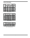
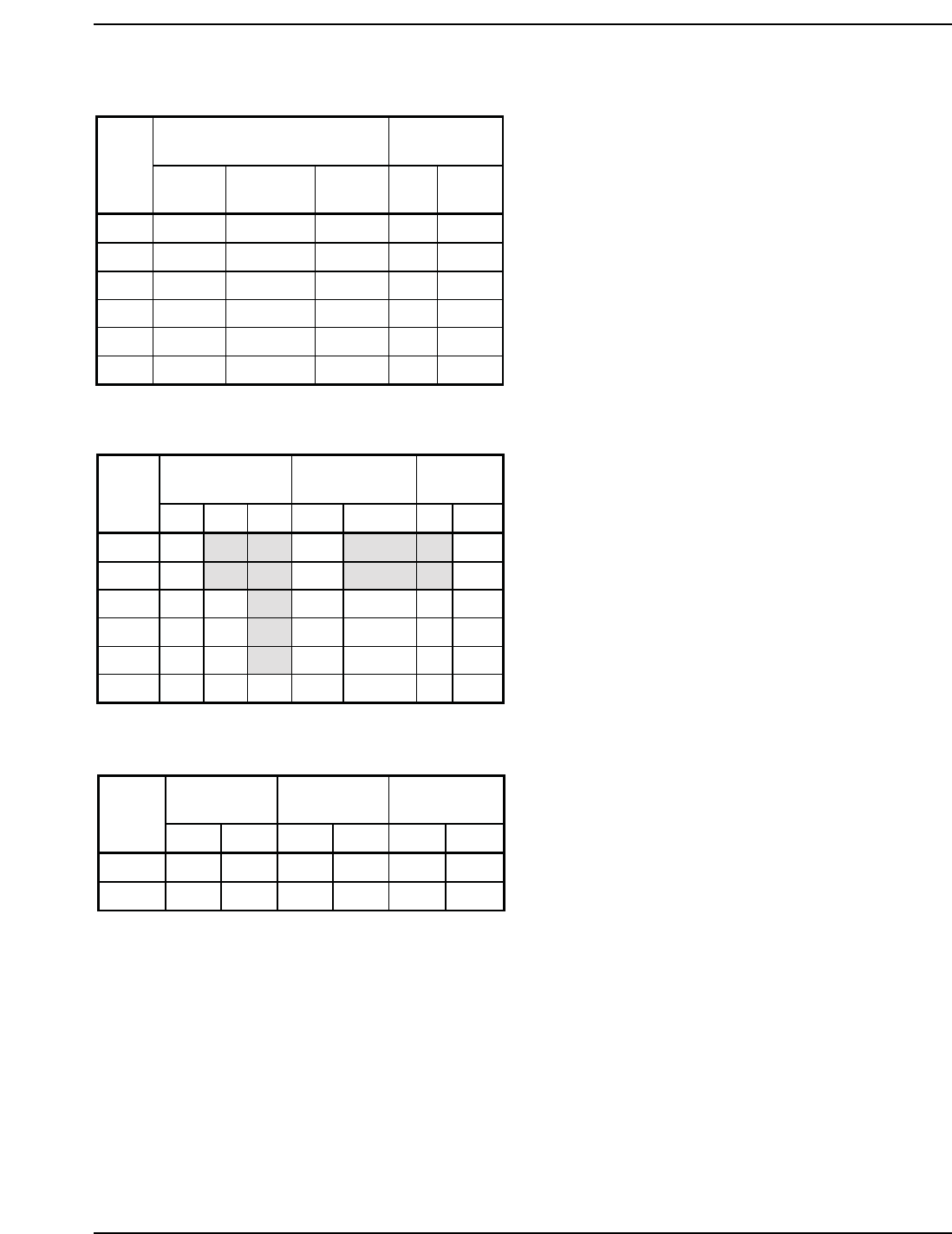
General Information
Quantity of
Vent Size
(in.)
Model
No.
Burners
Gas
Valves
Blowers Flue Intake
302A 6 1 1 5 6
402A 8 1 1 6 6
502A 10 2 1 6 6
652A 13 2 1 8 6
752A 15 2 1 8 6
902A 18 3 1 8 6
# Burners per
Valve
Stages
% Fire at
Stage
Model
No.
123 1 2 12
302A 6
1 100
402A 8 1 100
502A 5 5 11, 250100
652A 7 6 11,254100
752A 8 7 11,253100
902A 6 6 6 1, 1A 1, 1A, 2 66 100
Table A: Basic Data
Table B: Manifold Data
# Burners
per Valve
Valve
Staging
% Firing
at Stage
Model
No.
12*1 2 1 2
302A 4 2 1 1, 2 66 100
402A 5 3 1 1, 2 63 100
Table C: 2-Stage Design Option
* Valve 2 is inside the air plenum on H3/WH3 302A-402A


