


32
For installations in extremely cold climate, it is re-
quired that:
1. The vent must be installed with a slight upward
slope of not more than 1/4 inch per foot of hori-
zontal run to the vent terminal. In this case, an ap-
proved condensate trap must be installed per ap-
plicable codes.
2. The intake vent must be insulated through the
length of the horizontal run.
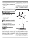
Termination
The flue direct vent cap MUST be mounted on the ex-
terior of the building. The direct vent cap cannot be
installed in a well or below grade. The direct vent cap
must be installed at least 1 ft above ground level and
above normal snow levels.
The direct vent cap MUST NOT be installed with any
combustion air inlet directly above a direct vent cap.
This vertical spacing would allow the flue products
from the direct vent cap to be pulled into the combus-
tion air intake installed above.
This type of installation can cause non-warrantable
problems with components and poor operation of the
heater due to the recirculation of flue products. Multi-
ple direct vent caps should be installed in the same
horizontal plane with a 4 ft clearance from the side of
one vent cap to the side of the adjacent vent cap(s).
Combustion air supplied from outdoors must be free of
particulate and chemical contaminants. To avoid a
blocked flue condition, keep the vent cap clear of
snow, ice, leaves, debris, etc.
The stainless steel flue direct vent cap must be fur-
nished by the heater manufacturer in accordance with
its listing (sales order option D-15).
Use only the special gas vent pipes listed for use with
Category III gas burning heaters, such as the AL29-4C
stainless steel vents offered by Heat Fab Inc. (800-
772-0739), Protech System, Inc. (800-766-3473) or Z-
Flex (800-654-5600). Pipe joints must be positively
sealed. Follow carefully the vent manufacturer’s instal-
lation instructions.
WARNING: No substitutions of flue pipe or vent
cap material are allowed. Such substitutions would
jeopardize the safety and health of inhabitants.
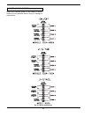
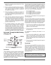
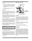
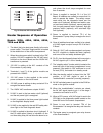
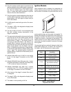
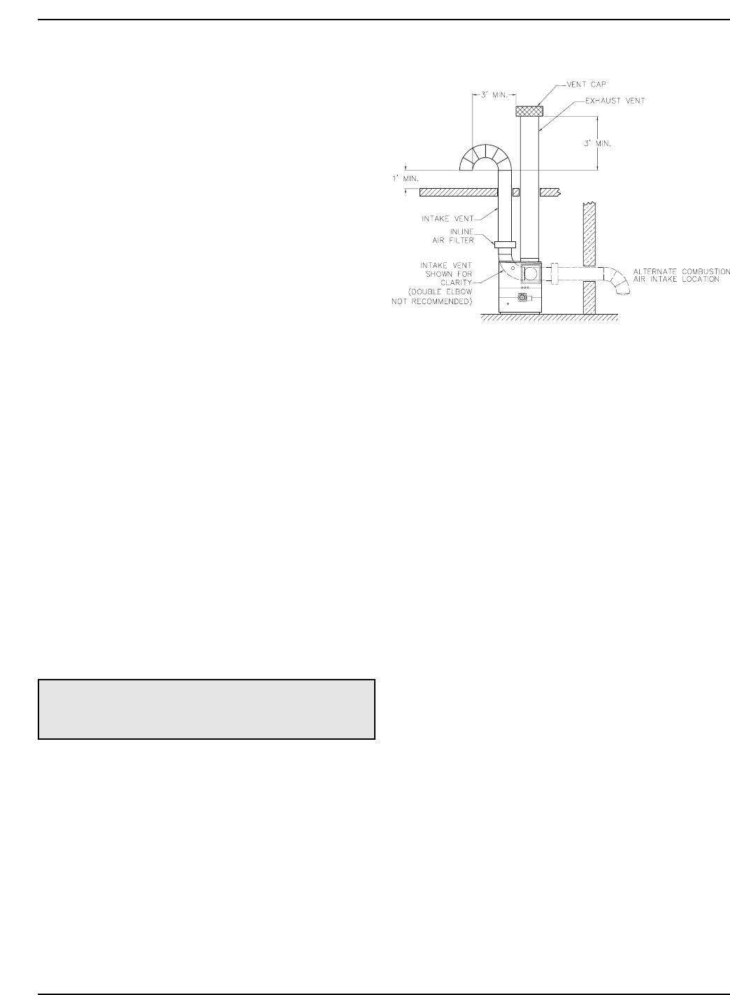
Direct Vent - Vertical
Installation
These installations utilize the heater-mounted blower
to draw combustion air from outdoors and force the
heated flue products through the vent pipe under posi-
tive pressure. The vent material must be in accor-
dance with the above instructions for vent materials.
Vent material must be listed by a nationally recognized
test agency.
The connection from the appliance flue to the stack
must be as direct as possible and should be the same
size or larger than the vent outlet.
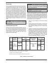
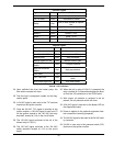
See Table L for Category I venting guidelines.
It is recommended that in colder climates, the intake
vent be insulated.
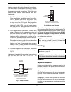
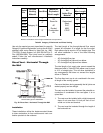
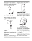
Termination
The flue terminal should be vertical and should termi-
nate outside the building at least 2 ft above the high-
est point of the roof within 10 ft. The vent cap should
have a minimum clearance of 4 ft horizontally from and
in no case above or below (unless a 4 ft horizontal dis-
tance is maintained) electric meters, gas meters, reg-
ulators and relief equipment. The distance of the vent
terminal from adjacent public walkways, adjacent
buildings, open windows and building openings must
be consistent with the NFGC (U.S.) or B149.1
(Canada).
Note: When vertical height exceeds 25 ft, consult
factory prior to installation.
Fig. 27: Direct Vent - Vertical