


35
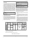
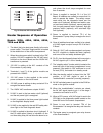
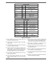
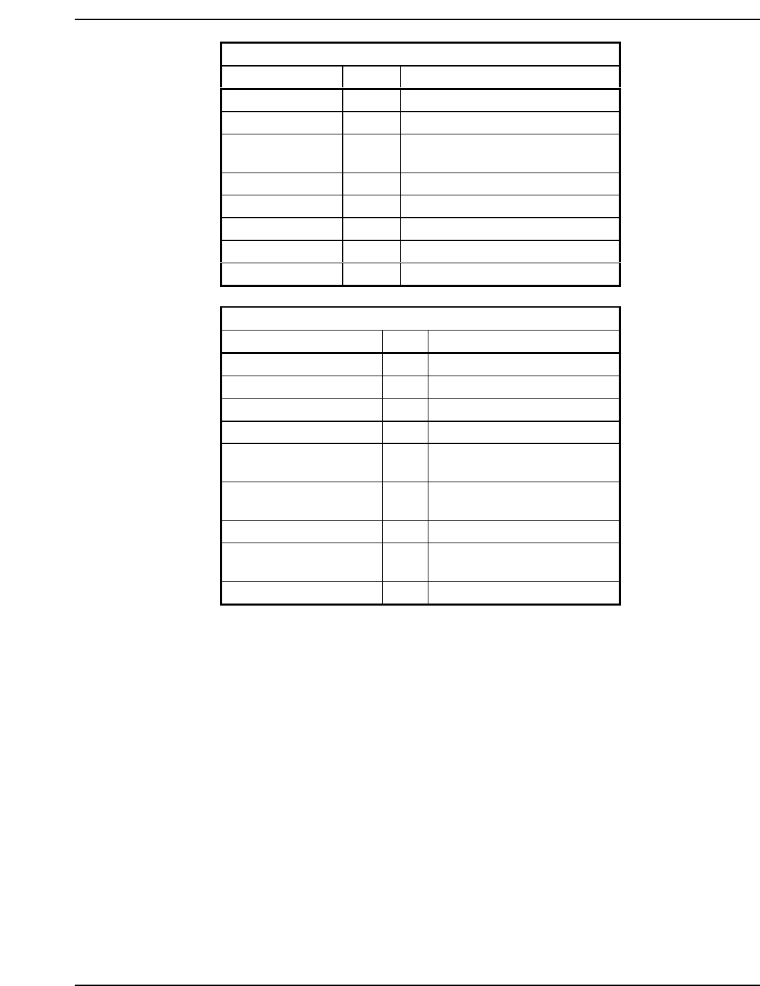
External Lights
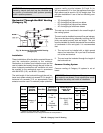
Light Color Indication
Power Blue Main power is on
Call For Heat Yellow Thermostat is closed
Safety Red
One or more safeties is inopera-
tive
Ignition Red Ignition module is inoperative
Flow Green Flow is present
Blower 1 Green Blower 1 is on
Stage 1 Green Stage 1 is on
Stage 2 Green Stage 2 is on
Internal Lights
Light Color Indication
Board Power Yellow Board power is on
Low Water Cut-Off Red Low water cut-off is open
Blocked Vent Red Vent is blocked
Manual Reset Hi-Limit Red Manual reset is open
Low Gas Pressure
Switch
Red Low gas pressure
High Gas Pressure
Switch
Red High gas pressure
(Not Used) Red
PVC Vent Limit Red
Vent temperature exceeds
limits
Auto Reset High Limit Red Auto reset option
Table N: LED Indicators
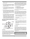
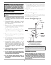
24. Upon sufficient flow from the heater pump, the
flow switch contacts will close.
25. The flow light is energized; located on the diag-
nostics panel.
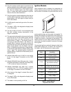
26. A 24 VAC signal is also sent to the “TH” terminal
located on the ignition module.
27. Once the 24 VAC “TH” signal is received at the
ignition module, a 120 VAC signal is sent from F2
on the ignition module to the 120 VAC pilot duty
terminals, located at J-14 on the circuit board.
28. The 120 VAC signal continues to the coil of the
blower relay K-3 (N.O.).
29. The 120 VAC signal continues to the 120 VAC
safety terminals located at J-13 on the circuit
board.
30. When the coil on relay K-3 (N.O.) is powered, the
relay contacts (K-3) close and energizes the blow-
er from the J-8 connections on the CPW board.
31. After proper air pressure is received in the air
plenum, the air pressure switch will close.
32. A 24 VAC signal is now sent to the blower LED on
the diagnostics board.
33. Power is applied to the optional equipment inter-
lock connection (normally jumpered).
34. The 24 VAC signal is then sent to the 24 VAC safe-
ty connector.
35. 24 VAC is now sent to the pressure switch (P.S.)
terminal on the ignition module.