


41
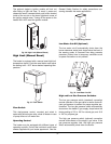
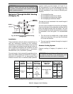
Horizontal Through-the-Wall Venting
(Category IV)
WARNING: Vent connectors serving appliances
vented by natural draft shall not be connected into
any portion of mechanical draft systems operating
under a positive pressure.
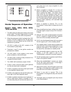
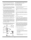
Fig. 38: Horizontal Through-the-Wall Venting
(Category IV)
Installation
These installations utilize the boiler-mounted blower to
vent the combustion products to the outdoors.
Combustion air is taken from inside the room and the
vent is installed horizontally through the wall to the out-
doors. Adequate combustion and ventilation air must
be supplied to the mechanical room in accordance
with the NFGC (U.S.) and B149.1 (Canada).
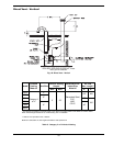
The total length of the horizontal through-the-wall ex-
haust vent system should not exceed 70 ft in length. If
horizontal run exceeds 70 ft, an appropriately sized
extractor must be used. To maintain proper operation,
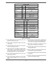
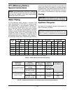
Air Inlet
Max. Length*
Model
Certified
Venting
Material
Vent Size
Maximum
Equivalent
Vent Length
Combustion Air
Intake Pipe
Material
6” 8”
302AE 5”
402AE
100’ N/A
502AE
6”
75’
652AE
752AE
40’
100’
902AE
Category II
or IV
8”
70’
Room Air
40’
Ducted
Combustion
Air
Galvanized Steel,
PVC,
ABS,
CPVC
30’ 80’
pressure reading must be between -0.01 and -0.1 in.
WC as measured 12 in. from the appliance flue outlet.
Each elbow used is equal to 10 ft of straight pipe. This
will allow installation in one of the four following com-
binations:
• 70’ of straight flue pipe
• 60’ of straight flue pipe and one elbow
• 50’ of straight flue pipe and two elbows
• 40’ of straight pipe and three elbows
The vent cap is not considered in the overall length of
the venting system.
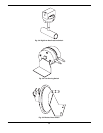
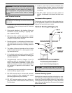
The vent must be installed to prevent flue gas leakage.
Care must be taken during assembly to ensure that all
joints are sealed properly and are airtight. The vent
must be installed to prevent the potential accumulation
of condensate in the vent pipes. It is recommended
that:
1. The vent must be installed with a slight upward
slope of not more than 1/4 in per foot of horizontal
run to the vent terminal.
2. The vent must be insulated through the length of
the horizontal run.
Common Venting System
Common venting of Category IV systems is not al-
lowed.
WARNING: No substitutions of flue pipe or vent
cap material are allowed. Such substitutions would
jeopardize the safety and health of inhabitants.
Table R: Category II and IV Venting
* Subtract 10 ft per elbow. Max. 3 elbows.
Maximum combustion air duct length terminated at 100 equivalent ft.