


39
87%-Efficiency Boilers –
Special Instructions
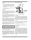
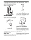
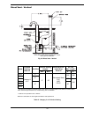
Water Piping
An 87%-efficiency boiler requires a minimum inlet
water temperature of 120ºF (49ºC) to prevent exces-
sive condensation in the combustion chamber. An
87%-efficiency boiler operated with an inlet tempera-
ture of less than 120ºF (49ºC) must have a manual
bypass or an approved low-temperature operation
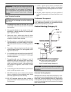
system to prevent problems with condensation. A man-
ual bypass, shown in Fig. 15, must be piped into the
system at the time of installation. This piping is like a
primary/secondary boiler installation with a bypass in
the secondary boiler piping. Raypak strongly recomm-
NOTE: The constructions of the 84%- (standard)
and 87%-efficiency (optional) boilers are very similar,
and they are installed to the same requirements,
except as noted in this section.
ends that a thermometer be placed into the boiler inlet
piping next to the in/out header to facilitate tempera-
ture adjustment. Inlet water temperatures below 120ºF
(49ºC) can excessively cool the products of combus-
tion, resulting in condensation on the heat exchanger.
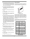
Venting
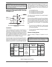
Appliance Categories
See Table Q for appliance category requirements for
the 87%-efficiency Hi Delta.
CAUTION: Proper installation of flue venting is criti-
cal for the safe and efficient operation of the boiler.
NOTE: For additional information on appliance cat-
egorization, see appropriate code NFGC (U.S.) and
B149.1 (Canada), or applicable local building codes.
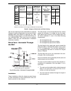
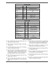
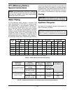
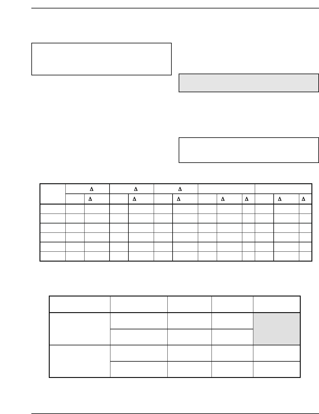
10°F T 20°F T 30°F T Min. Flow Max Flow
Model
No.
gpm
P (ft) gpm P (ft) gpm P (ft) gpm P (ft) Tgpm P (ft) T
302AE 52 3.3 26 <1.0 N/A N/A 20 <1.0 26 90 9.8 6
402AE 69 6.0 35 1.5 23 <1.0 20 <1.0 35 90 10.0 8
502AE 87 9.7 44 2.5 29 1.1 22 <1.0 40 90 10.4 10
652AE N/A N/A 57 4.4 38 2.0 28 1.1 40 90 10.8 13
752AE N/A N/A 65 6.1 44 2.8 33 1.6 40 90 11.3 15
902AE N/A N/A 78 8.9 52 4.1 39 2.3 40 90 11.7 17
Combustion
Air Supply
Exhaust
Configuration
Heater Venting
Category
Certified
Materials
Combustion Air
Inlet Material
Vertical Natural Draft
Venting
II
Stainless Steel
(Gas Tight)
From Inside Building
(Non-Direct Venting)
Horizontal Through-
the-Wall Venting
IV AL29-4C
Vertical Natural Draft
Venting
II
Stainless Steel
(Gas Tight)
Galvanized Steel
PVC
From Outside Building
(Direct Venting)
Horizontal Through-
the-Wall Venting
IV AL29-4C
ABS
CPVC
Table P: Heater Rate of Flow and Pressure Drop
Table Q: Category Determination for Venting Purpose and Venting Arrangement
Note: Basis for minimum flow is 20 gpm or 40°F ΔT. Basis for maximum flow is 90 gpm.