


29
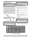
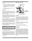
Termination
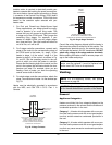
The vent terminal should be vertical and should termi-
nate outside the building at least 2 ft above the high-
est point of the roof that is within 10 ft. The vent cap
should have a minimum clearance of 4 ft horizontally
from and in no case above or below (unless a 4 ft hori-
zontal distance is maintained) electric meters, gas me-
ters, regulators and relief equipment. The distance of
the vent terminal from adjacent public walkways, adja-
cent buildings, open windows and building openings
must be consistent with the NFGC (U.S.) or B149.1
(Canada). Gas vents supported only by flashing and
extended above the roof more than 5 ft should be se-
curely guyed or braced to withstand snow and wind
loads.
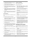
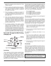
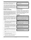
Common Venting System
Manifolds that connect more than one heater to a com-
mon chimney must be sized to handle the combined
load. Consult available guides for proper sizing of the
manifold and the chimney. At no time should the area
of the common vent be less than the area of the
largest heater exhaust outlet.
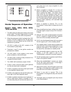
Common venting systems may be too large once an
existing unit is removed. At the time of removal of an
existing appliance, the following steps must be fol-
lowed with each appliance remaining connected to the
common venting system placed in operation, while the
other appliances remaining connected to the common
venting system are not in operation.
1. Seal any unused opening in the common venting
system.
2. Visually inspect the venting system for proper size
and horizontal pitch and verify there is no block-
age, restriction, leakage, corrosion or other unsafe
condition.
3. Insofar as is practical, close all building doors and
windows and all doors between the space in which
the appliances remaining connected to the com-
mon venting system are located and other spaces
of the building. Turn on clothes dryers and any ap-
pliance not connected to the common vent sys-
tem. Turn on any exhaust fans, such as range
hoods and bathroom exhausts, at maximum
CAUTION: A listed vent cap terminal, adequately
sized, must be used to evacuate the flue products
from the heaters.
WARNING: Vent connectors serving appliances
vented by natural draft shall not be connected into
any portion of mechanical draft systems operating
under a positive pressure.
CAUTION: Vent connectors for natural draft vent-
ing systems must be Type B or better.
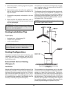
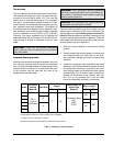
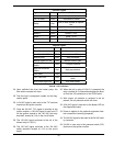
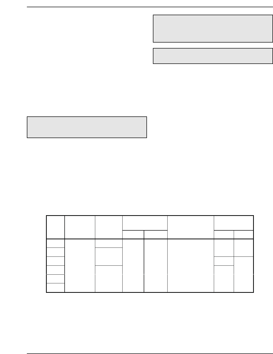
Vertical Venting
Height*
Air Inlet
Max. Length**
Model
Certified
Venting
Material
Vent Size
Min. Max.
Combustion Air
Intake Pipe
Material
6” 8”
302A 5”
402A
100’ N/A
502A
6”
75’
652A
752A
902A
Cat. I
(Type B
Equivalent)
8”
5’ 25’
Galvanized Steel,
PVC,
ABS,
CPVC
40’
100’
Table L: Category I Vertical Venting
* Vent lengths are based on a lateral length of 2 ft. Refer to the latest edition of the NFGC for further details. When
vertical height exceeds 25 ft, consult factory prior to installation.
** Subtract 10 ft per elbow. Max. 3 elbows.
Maximum combustion air duct length terminated at 100 equivalent ft.