


22
8. Remove the rubber grommet from the left-hand-
side panel and reinstall into the standard main gas
opening, located on the right-hand side of the
heater.
9. Install a coupling, nipple, union and sediment trap
onto the right-hand end of the main gas line and
then install the gas line, making sure that a manu-
al shut-off valve has been installed within 10 ft of
the heater.
10. Replace the left and right front panels on the
heater.
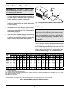
Gas Supply Pressure
A minimum of 5.0 in. WC and a maximum of 10.5 in.
WC upstream gas pressure is required under load and
no-load conditions for natural gas. A minimum of 11.0
in. WC and a maximum of 13.0 in. WC is required for
propane gas. The gas pressure regulator(s) supplied
on the heater is for low-pressure service. If upstream
pressure exceeds 14.0 in. WC, an intermediate gas
pressure regulator, of the lockup type, must be
installed.
When connecting additional gas utilization equipment
to the gas piping system, the existing piping must be
checked to determine if it has adequate capacity for
the combined load.
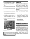
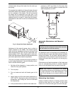
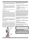
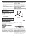
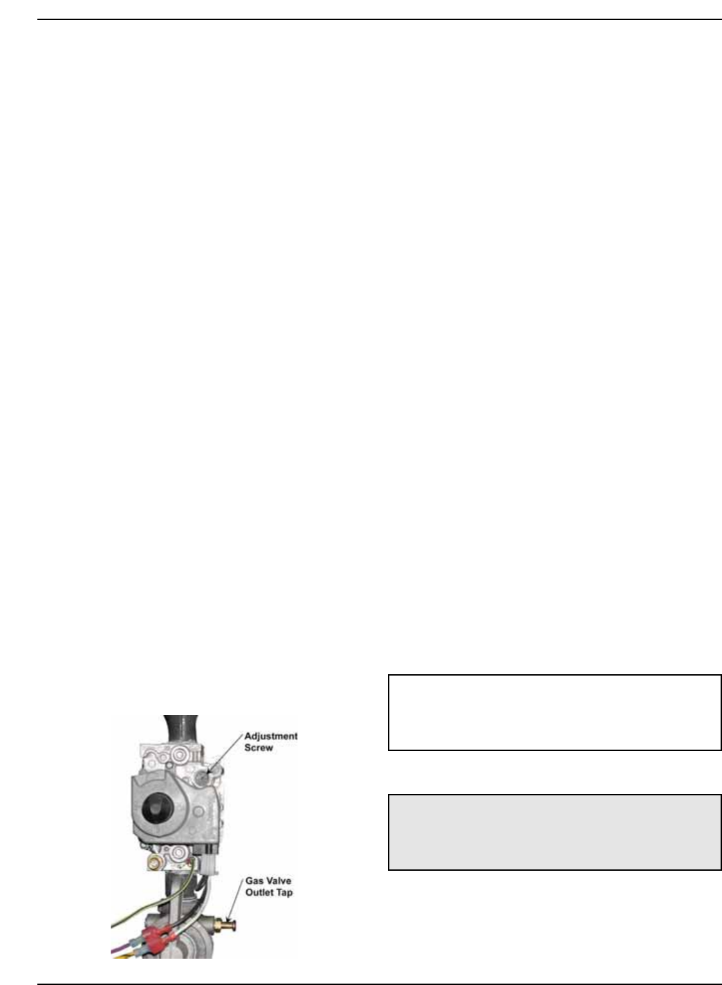
The gas valve pressure regulator(s) on the heater are
nominally preset at 3.5 in. WC for natural gas, and
10.5 in. WC for propane gas. The pressure at the gas
valve outlet tap, measured with a manometer, while in
operation should be 3.5 ± 0.1 in. WC for natural gas
and 10.5 in. ± 0.1 in. WC for propane gas. If an adjust-
ment is needed, remove the adjustment screw cover
and turn the adjustment screw clockwise to increase
pressure or counter-clockwise to lower pressure.
Fig. 17: Gas Valve
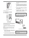
Electrical Power Connections
Installations must follow these codes:
• National Electrical Code and any other national,
state, provincial or local codes or regulations hav-
ing jurisdiction.
• Safety wiring must be NEC Class 1.
• Heater must be electrically grounded as required
by the NEC.
• In Canada, CSA C22. 1 C.E.C. Part 1.
The heater is wired for 120 VAC, 8 amps. The voltage
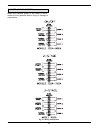
is indicated on the tie-in leads. Consult the wiring dia-
gram shipped with the heater in the instruction packet.
The remote tank control stat, thermostat, or electronic
heater control (as applicable) may be connected to the
stage selector terminal (See wiring diagram). 24 VAC
is supplied to this connection through the heater trans-
former. DO NOT attach any voltage to the stage se-
lector terminals. Before starting the heater check to
ensure proper voltage to the heater and pump.
Install a separate disconnect means for each load.
Use appropriately sized wire as defined by NEC, CSA
and/or local code. All primary wiring should be 125% of
minimum rating.
If any of the original wire as supplied with the heater
must be replaced, it must be replaced with 105°C wire
or its equivalent.
Field-Connected Controllers
It is strongly recommended that all individually-pow-
ered control modules and the heater should be sup-
plied from the same power source.
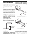
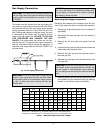
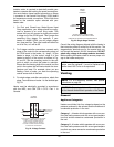
Check the Power Source
NOTE: Field-supplied isolation relays should be
installed when field-connected controllers are
mounted more than 50 equivalent feet (18 Ga) from
heater.
WARNING: Using a multi-meter, check the follow-
ing voltages at the circuit breaker panel prior to con-
necting any equipment. Make sure proper polarity is
followed and house ground is proven. (See Fig. 18.)