


23
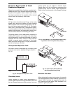
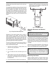
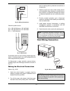
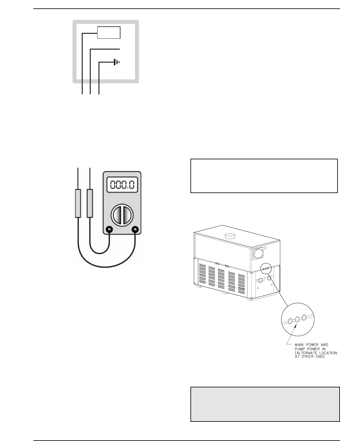
CIRCUIT
BREAKER
WHITE
GROUND
BLACK
GREEN
ABC
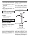
Fig. 18: Wiring Connections
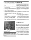
Check the power source:
AC = 108 VAC Minimum, 132 VAC MAX
AB = 108 VAC Minimum, 132 VAC MAX
BC = <1 VAC Maximum
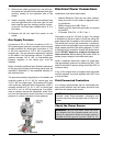
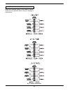
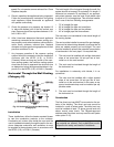
If the heater does not have a factory-wired stage con-
troller, it is factory-wired in an on-off configuration with
other stage terminals jumpered.
To field-connect a stage controller, remove factory-
installed jumper and wire stage controller as shown in
Fig. 21.
Making the Electrical Connections
Refer to Fig. 18-23.
1. Verify that circuit breaker is properly sized by
referring to heater rating plate. A dedicated circuit
breaker should be provided.
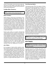
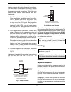
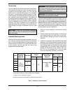
2. Turn off all power to the heater. Verify that power
has been turned off by testing with a multi-meter
Fig. 19: Multi-meter
prior to working with any electrical connections or
components.
3. Observe proper wire colors while making electri-
cal connections. Many electronic controls are po-
larity sensitive. Components damaged by improp-
er electrical installation are not covered by warran-
ty.
4. Provide overload protection and a disconnect
means for equipment serviceability as required by
local and state code.
5. Install heater controls, thermostats, or building
management systems in accordance with the
applicable manufacturers’ instructions.
6. Conduit should not be used as the earth ground.
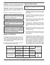
Field Wiring Connection
NOTE: A grounding electrode conductor shall be
used to connect the equipment grounding conduc-
tors, the equipment enclosures, and the grounded
service conductor to the grounding electrode.
CAUTION: Label all wires prior to disconnection
when servicing controls. Wiring errors can cause im-
proper and dangerous operation. Verify proper oper-
ation after servicing.
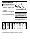
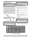
Fig. 20: Wiring Location