


48
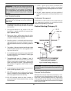
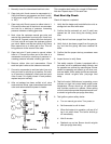
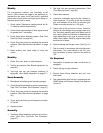
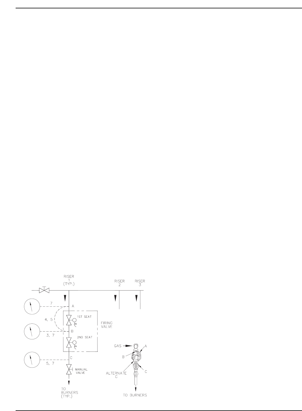
1. Manually close the downstream leak test valve.
2. Open test point A and connect a manometer to it.
Verify that there is gas pressure and that it is with-
in the proper range (NOTE: must not exceed 14.0
in. WC).
3. Open test point B and connect a rubber tube to it.
Connect the other end of the tube to a manometer
and look for a build-up of pressure. Increasing
pressure indicates a leaking gas valve.
4. Next, close the upstream manual gas valve and
remove the manometer from test point A and from
test point B. Connect a rubber tube from test point
A to test point B and open the upstream manual
gas valve. Make sure that test points A & B have
been opened so as to allow gas to flow. This will
bring pressure to the second valve seat.
5. Open test point C and connect a second rubber
tube to it. Connect the other end of the tube to a
manometer and look for a build-up of pressure. In-
creasing pressure indicates a leaking gas valve.
6. Remove rubber tube and manometers. Close
each test point valve as the tubes are removed.
7. Connect a manometer to each test point (one at a
time) and look for a build-up of pressure. If a build-
up of pressure is detected, check each test point
valve to see if it is tightly closed. If leak persists,
replace test point valve(s).
8. After no leakage has been verified at all valve
seats and test valves, open downstream leak tests
valve and restore electrical power to heater.
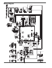
Fig. 41: Leak Test
This completes leak testing for a single Hi Delta mani-
fold riser. Repeat steps 1-8 for each riser.
Post Start-Up Check
Check off steps as completed:
1. Verify that the heater and heat distribution units or
storage tank are filled with water.
2. Confirm that the automatic air vent (if used) was
opened two full turns during the venting proce-
dure.
3. Verify that air has been purged from the system.
4. Verify that air has been purged from the gas pip-
ing, and that the piping has been checked for
leaks.
5. Confirm that the proper start-up procedures were
followed.
6. Inspect burner to verify flame.
7. Test safety controls: If heater is equipped with a
low water cut-off or additional safety controls, test
for operation as outlined by manufacturer. Burner
should be operating and should go off when con-
trols are tested. When safety devices are restored,
burners should re-ignite after pre-purge time
delay.
8. Test limit control: While burner is operating, move
indicator on high limit control below actual water
temperature. Burner should go off while blower
and circulator continue to operate. Raise setting
on limit control above water temperature and burn-
er should re-ignite after pre-purge time delay.
9. Test ignition system safety device:
a. Turn on manual gas valve. Turn power on.
b. Set thermostat to call for heat.
c. When the heater is in operation, pull cap off of
tee in air switch hose. The burner should go
off immediately.
d. Wait 5 minutes.
e. Reattach cap on tee. Burner should re-ignite
after pre-purge time delay.