


34
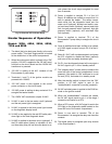
Fig. 28: External LED Indicator Decal
Heater Sequence of Operation
Models 302A, 402A, 502A, 652A,
752A and 902A
1. The black (hot) wire lead goes directly to the main
power switch. This black toggle switch is located
at the middle front of the control compartment.
2. When the main power switch is placed in the “ON”
position, 120 VAC is applied to the 120 VAC termi-
nal block on the circuit board and the 120/24 VAC
transformer is powered.
3. 120 VAC is waiting at the N.O. contacts of the
Economaster II pump delay.
4. Terminals L1 and F1 of the ignition module are
powered with 120VAC.
5. 120 VAC power is also applied to the control
power connector on the circuit board.
6. 120 VAC power is waiting at relay contacts K-3 to
energize the heater blower.
7. The 120/24 VAC transformer outputs 24 VAC.
8. 24 VAC is sent to the low water cut-off (optional)
and the red power light is energized.
9. 24 VAC is applied to the blue power light located
on the diagnostic display board.
10. 24 VAC is also applied to the red LED safety shut-
down light on the front diagnostic board.
11. 24 VAC is applied to the alarm circuit (optional). If
the E-5 sales option (Alarm) is included a 5 sec-
ond time delay relay will not allow the alarm to so-
und unless the circuit stays energized for more
than 5 seconds.
12. Power is applied to terminal P1-1 of the U-2
Board. All safeties are verified to ensure that it is
safe to operate the heater. The safety compo-
nents wired into the diagnostic board are: low
water cut-off (optional), blocked vent switch, man-
ual vent temp switch (optional), manual reset high
limit, low gas pressure switch (optional), high gas
pressure switch (optional), and auto-reset high
limit (optional).
13. Power is applied to terminal TP-1 of the
Economaster II pump delay to energize the circuit
board.
14. Once all safeties have been verified to be closed,
a 24 VAC signal is output from pin P3-16 of the U-
2 Board.
15. Relay K-1 (N.C.) will now be energized, and opens
the N.C. contacts to disable the alarm (optional)
and turns off the red safety shutdown light.
16. Pin P1-4 on the diagnostic board will now output a
24 VAC signal to pin 1 of the “standby switch”.
17. The “standby switch” (rocker switch) located at the
lower left front of the control compartment is now
powered. If the switch is “ON” and there is no call
for heat (CFH), the heater is in standby mode.
18. After the standby switch is placed into the “ON”
position, a 24 VAC signal is sent to the
“enable/disable” connection (normally jumpered).
19. 24 VAC switched power is applied to the S24V ter-
minal on the ignition module.
20. When the “enable/disable” contacts are closed,
the 24 VAC signal travels to pin 1 of the stage 1
connection and waits for a CFH.
21. When a CFH occurs, a 24 VAC signal is sent to the
CFH light on the diagnostics panel located on the
lower left front of the control compartment.
22. Power is now sent to terminal TP4 of the
Economaster II to energize the relay and close the
contacts.
23. The heater pump is energized upon relay closure
of the Economaster II.