


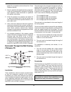
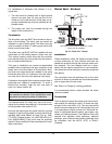
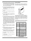
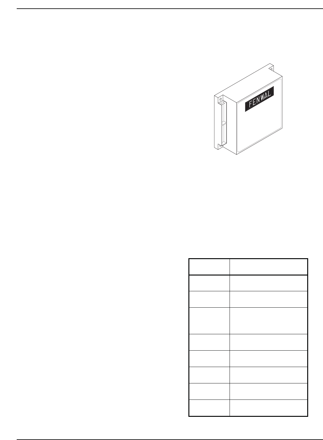
Ignition Module
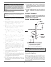
When additional heat is needed, the combustion air
blower starts to purge air from the combustion cham-
ber for about 15 seconds. On proof-of-air flow, the air-
proving switch closes and the igniter is energized. To
ensure safe operation, the gas valve cannot open until
the igniter is verified. The main burner is automatically
lit when the device is powered and pre-purged. The
heater performs its own safety check and opens the
main valve only after the igniter is proven to be capa-
ble of ignition.
The standard ignition module will attempt to light three
times before locking out. To reset it, turn off power to
the heater, wait 30 seconds and re-apply power.
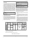
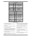
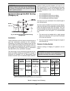
Code Condition
On
System OK;
No faults present
Off
Possible control fault;
Check power
1 Flash
Low air pressure, brief flash-
ing normal on start-up
2 Flashes
Flame in combustion
chamber; No call for heat
3 Flashes Ignition lockout
4 Flashes Low igniter current
5 Flashes
Low 24VAC, check control
supply voltage
6 Flashes
Internal fault;
Replace control
Fig. 29: Ignition Module
Table O: Ignition Module
Diagnostic LED Codes
36
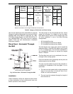
36. Once the pressure switch signal is received at the
ignition module the hot surface igniter is energized
by a 120 VAC signal from S-1 on the ignition mod-
ule. (The hot surface igniter must draw greater
than 3.1 amps while being energized or ignition
lockout will occur after three tries.)
37. Once the ignition module determines that the hot
surface igniter amp draw is within specs and oper-
ating properly, a 24 VAC signal is output from pin
GV on the module.
38. 24 VAC signal is received to gas valve 1 thus ener-
gizing it.
39. The stage 1 LED on the diagnostics display board
is now illuminated.
40. The coil of relay K-2 (N.O.) is now energized with
the (K-2) contacts closing downstream of the
stage 2 connections.
41. The gas coming through the burners should ignite
from the heat of the hot surface igniter and the
flame should carry over from one burner to the
other burners of stage 1. The remote sensor is
now trying to sense the flame. If the flame is not
sensed within 4 seconds, the ignition module will
shut down the gas valve and retry the hot surface
igniter. During ignition retry the heater must per-
form a 15-second pre-purge and an approximate-
ly 30-second igniter warm-up before opening gas
valve 1 again. The standard ignition module will
attempt ignition a maximum of three times prior to
ignition lockout.
42. (Models 302A-402A only) 24 VAC is now waiting
at pin 3 of the stage 2 connection on the CPW
board.
43. (Models 502A-902A only) After gas valve 1 opens
and flame rectification is received, time delay relay
1 (TD-1) starts a 5-second countdown.
44. (Models 502A-902A only) After the 5 second
countdown from TD-1, 24 VAC is waiting at pin 3
of the stage 2 connection on the CPW board.
45. After closure of the stage 2 contacts Gas valve 2
in energized.
46. The stage 2 LED on the diagnostics display board
is now illuminated.
47. The heater is now operating at full fire.