


27
8. Locate and guard vent termination to prevent acci-
dental contact by people or pets.
9. DO NOT terminate vent in window well, stairwell,
alcove, courtyard or other recessed area.
10. DO NOT terminate above any door, window, or
gravity air intake. Condensate can freeze, causing
ice formations.
11. Locate or guard vent to prevent condensate from
damaging exterior finishes. Use a rust-resistant
sheet metal backing plate against brick or mason-
ry surfaces.
12. DO NOT extend exposed vent pipe outside of
building. Condensate could freeze and block vent
pipe.
U.S. Installations
Refer to the latest edition of the National Fuel Gas
Code.
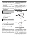
Vent termination requirements are as follows:
1. Vent must terminate at least 4 ft below, 4 ft hori-
zontally from or 1 ft above any door, window or
gravity air inlet to the building.
2. The vent must not be less than 7 ft above grade
when located adjacent to public walkways.
3. Terminate vent at least 3 ft above any forced air
inlet located within 10 ft.
4. Vent must terminate at least 4 ft horizontally, and
in no case above or below unless 4 ft horizontal
distance is maintained, from electric meters, gas
meters, regulators, and relief equipment.
5. Terminate vent at least 6 ft away from adjacent
walls.
6. DO NOT terminate vent closer than 5 ft below roof
overhang.
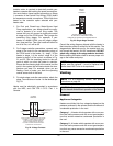
7. The vent terminal requires a 12 in. vent terminal
clearance from the wall.
8. Terminate vent at least 1 ft above grade, including
normal snow line.
9. Multiple direct vent installations require a 4 ft
clearance between the ends of vent caps located
on the same horizontal plane.
Canadian Installations
Refer to latest edition of B149.1.
A vent shall not terminate:
1. Directly above a paved sidewalk or driveway
which is located between two single-family dwell-
ings and serves both dwellings.
2. Less than 7 ft (2.13 m) above a paved sidewalk or
paved driveway located on public property.
3. Within 6 ft (1.8 m) of a mechanical air supply inlet
to any building.
4. Above a meter/regulator assembly within 3 ft (915
mm) horizontally of the vertical centre-line of the
regulator.
5. Within 6 ft (1.8 m) of any gas service regulator
vent outlet.
6. Less than 1 ft (305 mm) above grade level.
7. Within the 3 ft (915 mm) of a window or door which
can be opened in any building, any non-mechani-
cal air supply inlet to any building or the combus-
tion air inlet of any other appliance.
8. Underneath a verandah, porch or deck, unless the
verandah, porch or deck is fully open on a mini-
mum of two sides beneath the floor, and the dis-
tance between the top of the vent termination and
the underside of the verandah, porch or deck is
greater than 1 ft (305 mm).
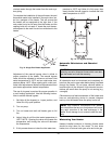
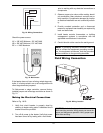
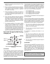
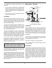
Changing the Flue Outlet
Follow these instructions to change the flue connec-
tion from the standard top location to the rear of the
heater.
1. Disconnect all electrical power from the heater (if
applicable).
2. Disconnect or isolate the main gas pipe from the
heater (if applicable).
3. Remove the screws, gasket and dustcover from
the rear of the heater.
4. Remove the screws, stainless steel flue cover and
gasket from the branch side of the tee located in
the flue box at the rear of the heater.