


51
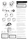
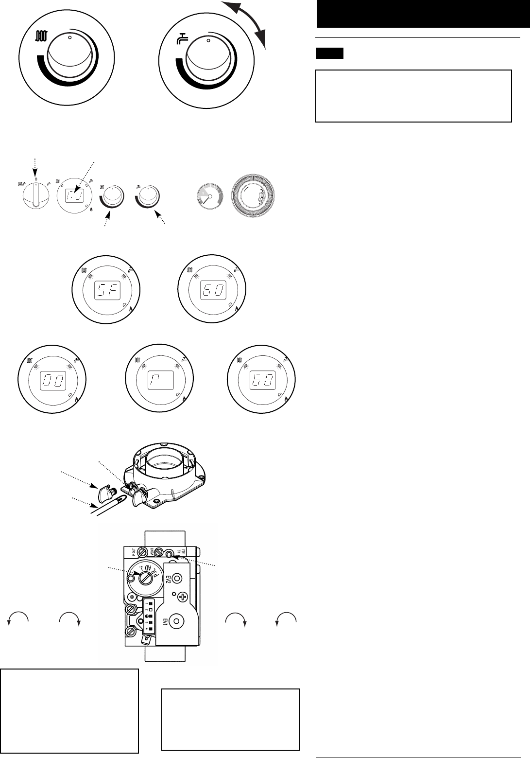
15.0 Setting the Gas Valve
© Baxi Heating UK Ltd 2012
Selector Switch
Display
Reset
1
2
3
4
5
PM
7
8
9
10
11
12
1
2
3
4
5
AM
7
8
9
10
11
12
0
bar
0
2
3
4
Central Heating
Temperature Control
Domestic Hot Water
Temperature Control
Fig. 103
Fig. 104
Fig. 105
Fig. 106 Fig. 107
Central Heating
Temperature Control
Domestic Hot Water
Temperature Control
Fig. 102
x 2
Fig. 108
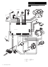
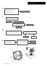
Throttle
Adjustment Screw
(cover removed)
Offset
Adjustment Screw
(cap fitted)
Gas Valve
Fig. 109
Flue Adaptor Test
Point
Plug
Analyser Probe
15.1 Setting the Gas Valve (CO
2
check)
IMPORTANT: The CO
2
must be only be checked and
adjusted to set the valve if a suitable calibrated
combustion analyser is available, operated by a
competent person - see Section 13.1
1. The combustion (CO
2
) may be checked after running the
boiler for several minutes. To do this it is necessary to set
the boiler to ‘Calibration Mode’.
2. Ensure that all external controls are calling for heat. The
actual current boiler temperature is shown on the display.
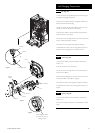
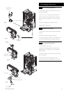
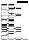
3. Turn both control knobs fully anticlockwise, then quickly
turn the right hand knob
1
/
4
clockwise twice and back fully
anticlockwise (Fig. 102).
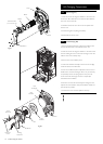
4. The display will now alternate between ‘SF’ and the
current boiler temperature and both green LEDs will flash
(Figs. 103 & 104).
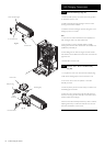
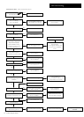
5. Turn the left hand knob fully clockwise. As the knob is
turned the display will change, indicating the fan speed.
6. The display will show ‘00’, indicating maximum rate, then
revert to ‘P ‘ alternating with the current boiler temperature
(Figs. 105, 106 & 107).
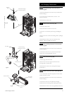
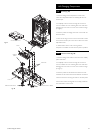
7. Remove the plug from the flue sampling test point. Insert
the analyser probe and allow sufficient time for the reading
to settle (Fig. 108).
The CO
2
should be 8.7% ± 0.2
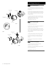
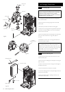
8. It is possible to alter the CO
2
by adjustment of the gas
valve. Remove the plastic cover from the Throttle
Adjustment Screw. At maximum rate the Throttle
Adjustment Screw should be turned, using a suitable
hexagon key, until the correct reading is obtained (Fig. 109).
Turning clockwise will reduce the CO
2
. Anticlockwise will
increase th e CO
2
.
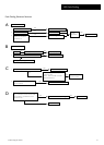
9. The CO
2
must then be checked at minimum rate. Turn
the left hand knob fully anti-clockwise. As the knob is turned
the display will change, indicating the fan speed. When the
display reads ‘ 0’ the boiler runs at minimum rate.
The CO
2
should be 8.4% ± 0.2
10. With the boiler on minimum, the Offset Adjustment
Screw must be altered, using a suitable hexagon key, after
removing the cap (Fig. 109). Turning anti-clockwise will
reduce the CO
2
. Clockwise will increase th e CO
2
.
11. The ‘Calibration Function’ is maintained for 20 minutes
unless the maximum CH temperature is exceeded. The
function can be disabled at any time by turning the right
hand knob.
12. Check the Combustion Performance (CO/CO
2
ratio).
This must be less than 0.004.
If the CO
2
is reset at minimum
rate it must be rechecked at
maximum rate again and adjusted
if required. If the CO
2
is reset at
maximum rate it must be
rechecked at minimum rate and
adjusted if required.
Do not turn the adjustment
screws more than 1/8 of a turn at
a time. Allow the analyser reading
to settle before any further
adjustment
Reduce CO
2
at min. rate
Increase CO
2
at min. rate
Reduce CO
2
at max. rate
Increase CO
2
at max. rate