


40
13.0 Servicing
© Baxi Heating UK Ltd 2012
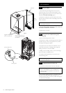
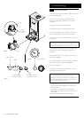
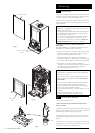
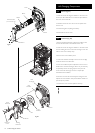
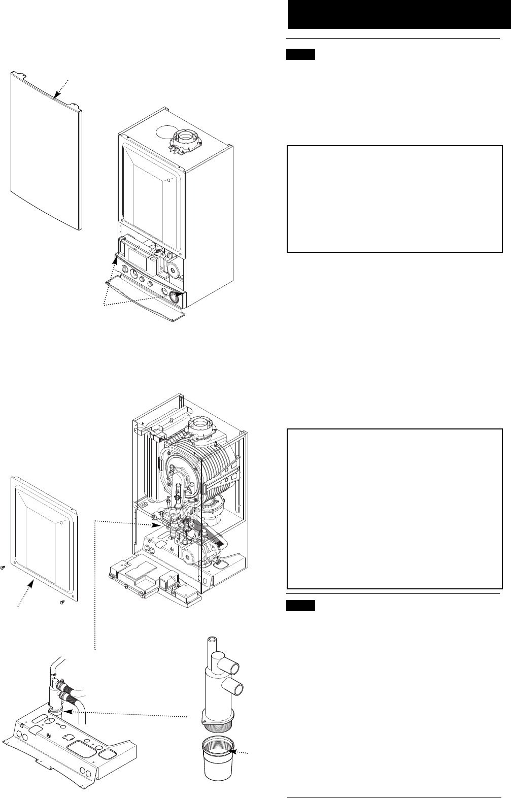
Case Front Panel
Fig. 69
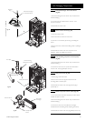
Facia Panel Securing
Screws
Fig. 70
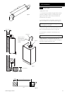
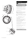
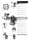
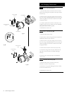
Inner Door
Panel
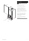
Fig. 71
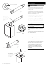
Sump
13 .1 Annual Servicing
1. For reasons of safety and economy, it is recommended that
the boiler is serviced annually. Servicing must be performed by
a competent person in accordance with B.S. 7967-4.
2. After servicing, complete the relevant Service Interval Record
section of the Benchmark Commissioning Checklist at the rear
of this publication.
IMPORTANT:During routine servicing, and after any
maintenance or change of part of the combustion circuit, the
following must be checked:-
•The integrity of the complete flue system and the flue seals.
•The integrity of the boiler combustion circuit and relevant
seals as described in Section 13.2.
•The operational gas inlet pressure as described in Section
11.2.1 to 11.2.7 and the gas rate as described in 11.2.8.
•The combustion performance as described in ‘Check the
Combustion Performance’ (13.1.4 to 13.1.6 below).
3. Competence to carry out Checking Combustion
Performance
B.S. 6798 ‘Specification for Installation & Maintenance of Gas
Fired Boilers not exceeding 70kW’ advises that:-
• The person carrying out a combustion measurement should
have been assessed as competent in the use of a flue gas
analyser and the interpretation of the results.
• The flue gas analyser used should be one meeting the
requirements of BS7927 or BS-EN50379-3 and be calibrated
in accordance with the analyser manufacturers’ requirements.
• Competence can be demonstrated by satisfactory
completion of the CPA1 ACS assessment, which covers the
use of electronic portable combustion gas analysers in
accordance with BS 7967, Parts 1 to 4.
Check the Combustion Performance (CO/CO
2
ratio)
4. Set the boiler to operate at maximum rate as described in
Section 15.1.1 to 15.1.6.
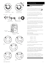
5. Remove the plug from the flue sampling point, insert the
analyser probe and obtain the CO/CO
2
ratio. This must be
less than 0.004.
6. If the combustion reading (CO/CO
2
ratio) is greater than
this, and the integrity of the complete flue system and
combustion circuit seals has been verified, and the inlet gas
pressure and gas rate are satisfactory either:
•Perform the ‘Annual Servicing - Inspection’ (Section 13.2) &
re-check
•Adjust the gas valve (Section 15.0) & re-check
•Replace the gas valve (Section 14.24) & re-check
13.2 Annual Servicing - Inspection
1. Ensure that the boiler is cool.
2. Ensure that both the gas and electrical supplies to the
boiler are isolated.
3. Slacken the screws securing the facia panel. Lift the outercase
panel so that its securing tabs are clear of the facia. Remove the
panel, allowing the facia to hinge down (Fig. 69).
4. Remove the screws securing the inner door panel. Lift the
panel slightly to disengage it from the studs on top of the case
(Fig. 70).
5. Unscrew the sump from the bottom of the condensate trap
assembly (Fig. 71) and remove any deposits from the sump and
trap. Clean as necessary and replace the sump.