


30
© Baxi Heating UK Ltd 2012
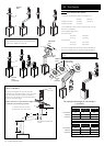
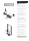
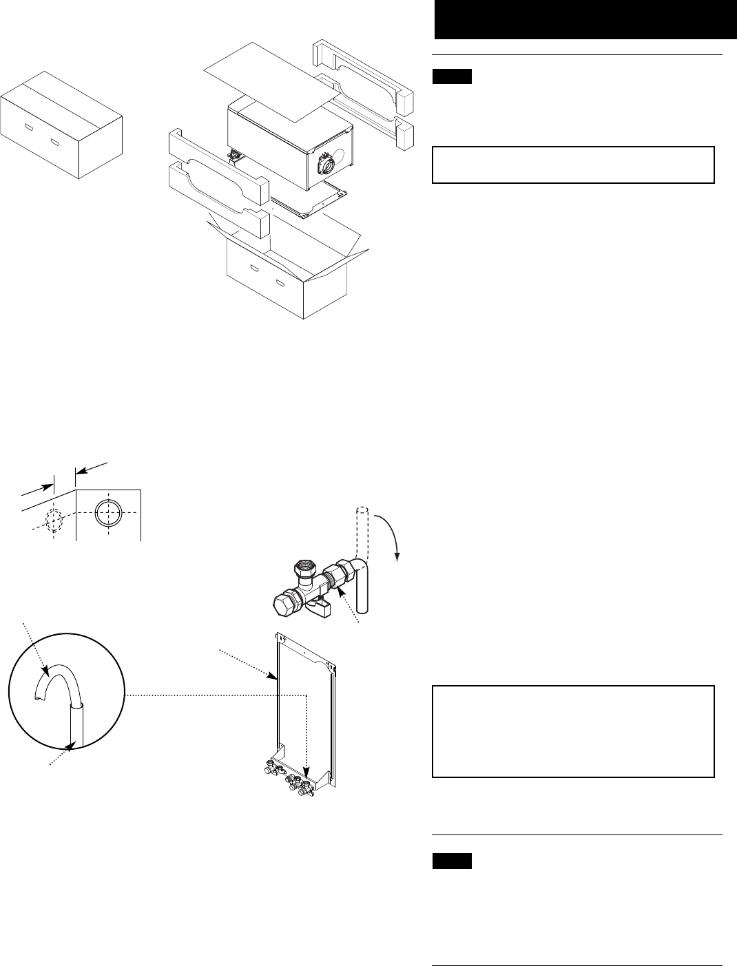
Fig. 42
145mm
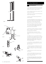
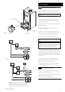
For Side Flue Exit
Central Heating Return
Flushing Tube
Wall Plate
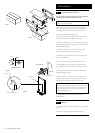
Fig. 41
Fig. 39
Fig. 40
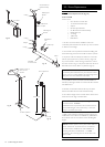
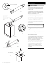
10.0 Installation
10.1 Unpacking & Initial Preparation
The gas supply, gas type and pressure must be checked for
suitability before connection (see Section 7.4).
NOTE: A small amount of water may drain from the
boiler in the upright position.
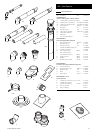
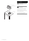
1. Remove staples, open flaps and remove the cardboard
sheet. Remove the polystyrene side pieces and literature.
Two people can then lift out the boiler (Figs. 39 & 40).
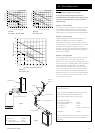
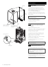
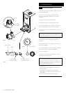
2. After considering the site requirements
(see Section 7.0) position the fixing template on the wall
ensuring it is level both horizontally and vertically.
3. Mark the position of the two most suitable fixing slots for
the wall plate and boiler lower fixing holes. It is preferable to
use the vertical fixing slots.
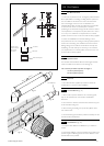
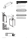
4. Mark the position of the centre of the flue hole (rear
exit). For side flue exit, mark as shown (Fig. 41).
5. If required, mark the position of the gas and water pipes.
Remove the template.
6. Cut the hole for the flue (minimum diameter 116mm).
7. Drill the wall as previously marked to accept the wall
plugs supplied. Secure the wall plate using the fixing screws.
8. Using a spirit level ensure that the plate is level before
finally tightening the screws.
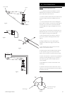
9. Connect the gas and water pipes to the valves on the
wall plate using the copper tails supplied. Ensure that the
sealing washers are fitted between the connections.
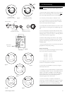
IMPORTANT: ONLY on 40 models the Cold Water
Inlet tap is fitted with a flow regulator. The copper tail is
factory fitted on this model, but must be loosened and
turned through 180° to point downwards. Ensure the
joint is fully tight (Fig. 42a).
10. Fit the filling loop as described in the instructions
supplied with it.
10.2 Flushing
1. Connect a tube to the central heating flow or return pipe
(Fig. 42).
2. Flush thoroughly (see System Details, Section 6.2).
40 model only
Fig. 42a
Flow Regulator