


37
11.0 Commissioning
© Baxi Heating UK Ltd 2012
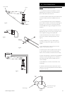
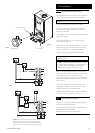
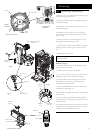
11.2 Check the Operational (Working) Gas Inlet
Pressure
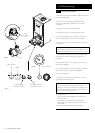
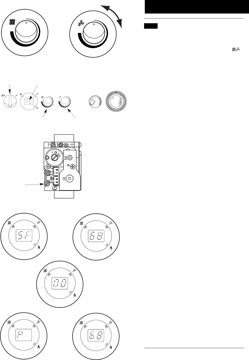
1. Ensure that all controls are calling for heat, and the selector
switch is in the central heating and hot water position ( ).
The current boiler temperature is shown on the display.
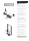
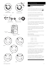
2. It is necessary to set the boiler to ‘Calibration Mode’.
3. Turn both temperature control knobs fully anticlockwise,
then quickly turn the DHW temperature knob
1
/
4
clockwise
twice and back fully anticlockwise (Fig. 62).
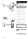
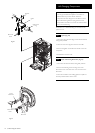
4. The display will now alternate between ‘SF’ and the current
boiler temperature and both green LEDs will flash (Figs. 63 &
64).
5. Turn CH temperature control knob fully clockwise. As the
knob is turned the display will change from ‘0’ to ‘00’ (Fig. 65)
indicating maximum rate, then revert to ‘P’ alternating with the
current boiler temperature (Figs 66 & 67).
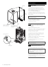
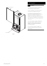
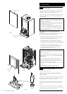
6. With the boiler operating in the maximum rate condition
check that the operational (working) gas pressure at the inlet
gas pressure test point (Fig. 62a) is in accordance with B.S.
6798 & B.S. 6891.
7. Ensure that this inlet pressure can be obtained with all other
gas appliances in the property working.
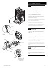
Measure the Gas Rate
8. With any other appliances & pilot lights turned OFF the gas
rate can be measured. It should be between:-
24 model 2.6m
3
/h
28 model 3.1m
3
/h
33 model 3.6 m
3
/h
40 model 4.36 m
3
/h
9. The ‘Calibration Function’ is active for 20 minutes unless the
maximum CH temperature is exceeded.
10. The function can be disabled at any time by turning the
DHW temperature knob.
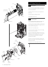
11. Carefully read and complete all sections of the Benchmark
Commissioning Checklist at the rear of this publication that are
relevant to the boiler and installation. These details will be
required in the event of any warranty work. The publication
must be handed to the user for safe keeping and each
subsequent regular service visit recorded.
12. For IE, it is necessary to complete a “Declaration of
Conformity” to indicate compliance with I.S. 813. An example
of this is given in I.S. 813 “Domestic Gas Installations”. This is
in addition to the Benchmark Commissioning Checklist.
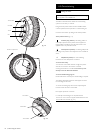
Selector Switch
Display
Reset
1
2
3
4
5
PM
7
8
9
10
11
12
1
2
3
4
5
AM
7
8
9
10
11
12
0
bar
0
2
3
4
Central Heating
Temperature Control
Domestic Hot Water
Temperature Control
Fig. 63
Fig. 64
Fig. 65
Fig. 66
Fig. 67
Central Heating
Temperature Control
Domestic Hot Water
Temperature Control
Fig. 62
x 2
Gas Valve
Gas Pressure
Test Point
Fig. 62a