


49
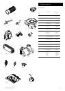
14.0 Changing Components
© Baxi Heating UK Ltd 2012
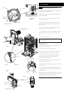
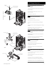
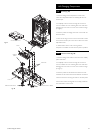
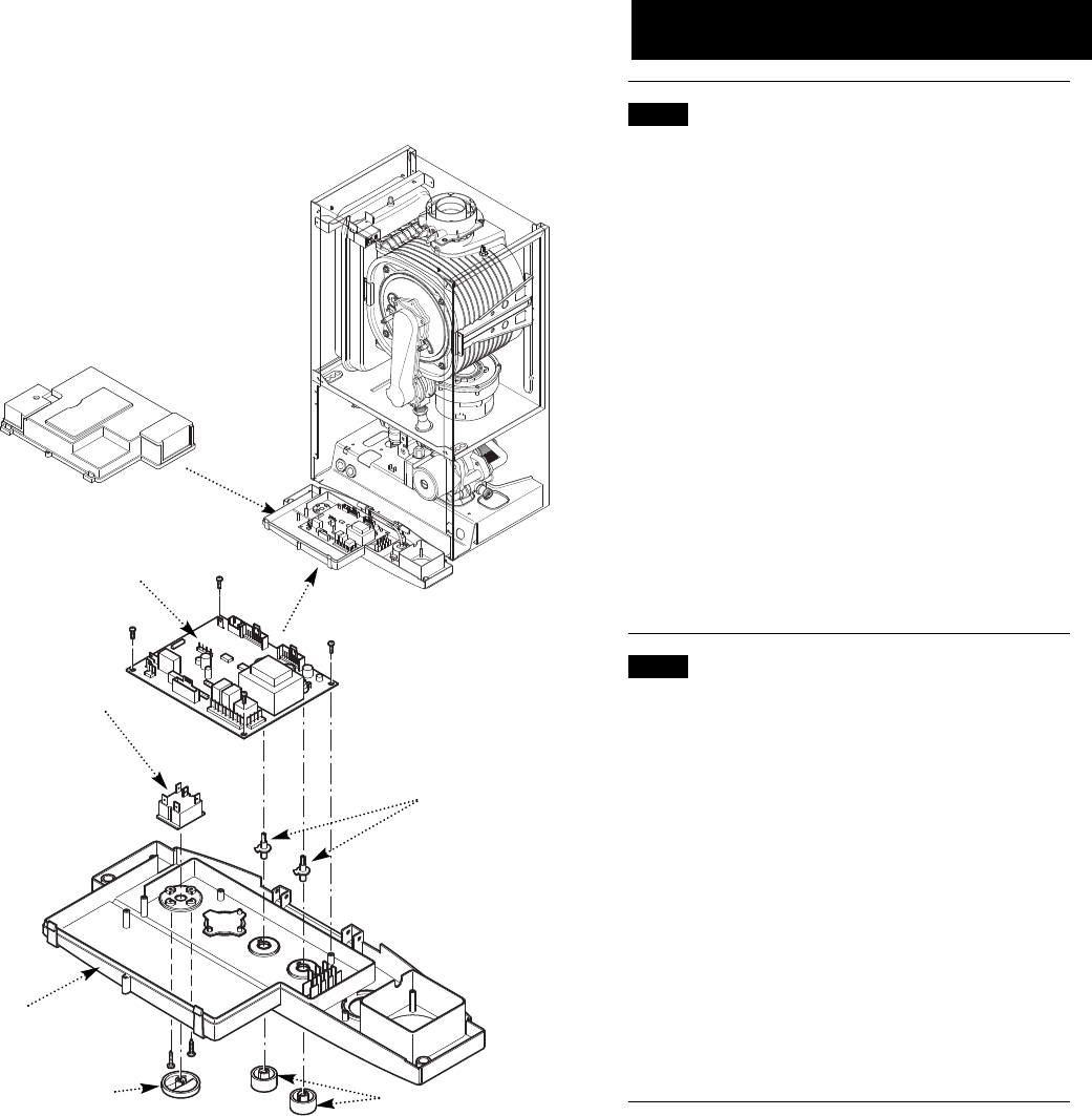
14.22 P.C.B. (Fig. 98)
1. Note the settings of the temperature control knobs,
rotate them fully anticlockwise and carefully pull them off
the drive pins.
2. Completely undo the screws securing the control box
cover and release the cover retaining barbs from their slots.
Disengage the rear of the cover from the control box hinge
pin (Fig. 97).
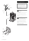
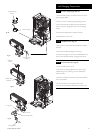
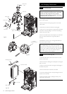
3. Note the position of all plugs and wires on the P.C.B. and
disconnect them.
4. Undo the securing screws and remove the P.C.B. Transfer
the control knob drive pins to the new P.C.B. and turn them
fully anticlockwise.
5. Reassemble in reverse order, ensuring that the
temperature controllers are reset to their previous positions.
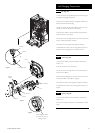
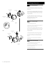
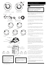
14.23 Selector Switch (Fig. 98)
1. Note the setting of the selector switch knob and carefully
pull it off the facia.
2. Completely undo the screws securing the control box
cover and release the cover retaining barbs from their slots.
Disengage the rear of the cover from the control box hinge
pin (Fig. 97).
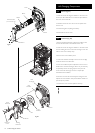
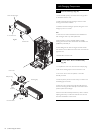
3. Note the position of the electrical connections and the
orientation of the switch. Remove the electrical connections.
4. Remove the screws securing the switch to the facia panel.
5. Fit the new switch, ensuring that it is correctly positioned
and reassemble in reverse order.
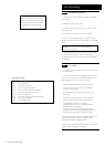
Control Box Cover
P.C.B.
Selector
Switch
Facia
Selector Switch Knob
Temperature Control Knobs
Fig. 97
Fig. 98
Drive Pins