


10
4.0 Technical Data
© Baxi Heating UK Ltd 2012
4.1 Titanium 24, 28, 33 & 40
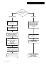
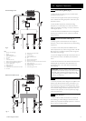
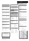
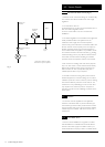
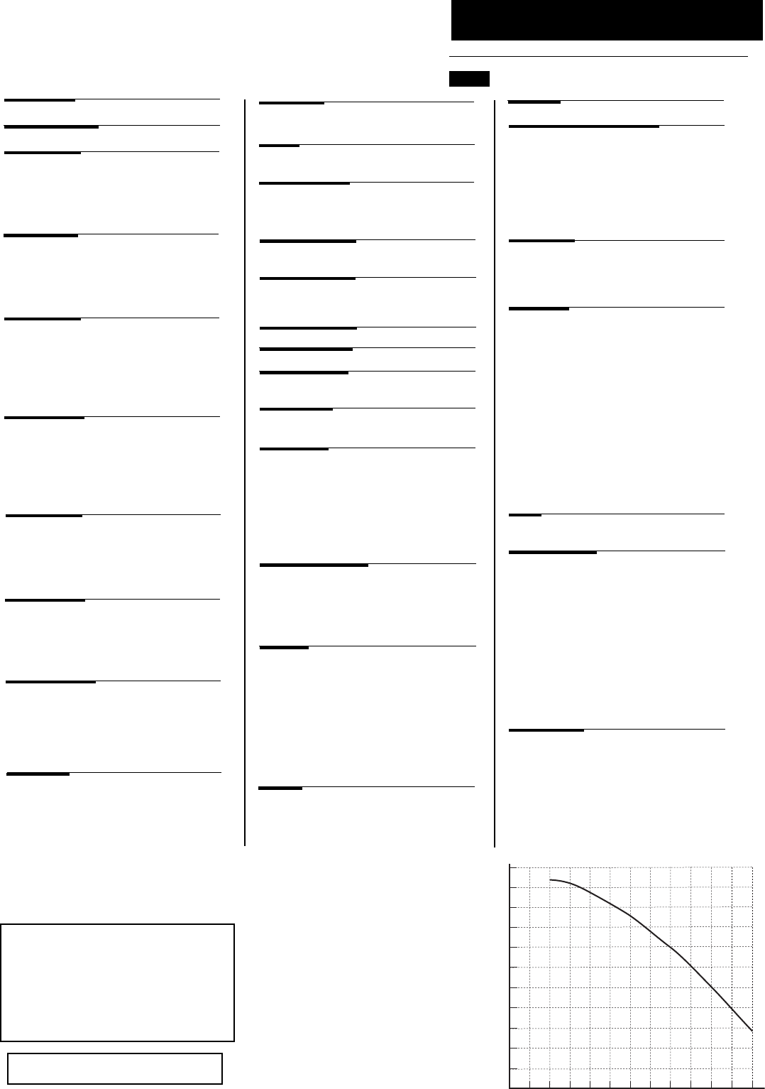
0
200 400 600 800 1000 1200
0.5
1
1.5
2
2.5
3
3.5
4
Metre (wg)
Flow Rate (l/h)
Pump - Available Head
0
5
5.5
4.5
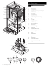
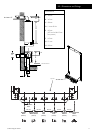
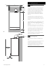
Flue Terminal Diameter 100mm
Dimensions Projection 125mm
Outercase Dimensions
Casing Height - 780mm
Overall Height Inc Flue Elbow - 965mm
Casing Width - 450mm
Casing Depth - 345mm
Weights
(24 model)
Packaged Boiler Carton 48.6 kg
Installation Lift Weight 43.6 kg
(28 model)
Packaged Boiler Carton 49.2 kg
Installation Lift Weight 44.2 kg
(33 & 40 model)
Packaged Boiler Carton 51kg
Installation Lift Weight 46kg
Central Heating Primary Circuit
Pressures
bar
Safety Discharge 3
Max Operating 2.5
Min Operating 0.5
Recommended Operating Range 1-2
DHW Circuit bar
Pressures
Max Operating 8
Min Operating 0.15
Flow Rates (24) (28) (33) (40)
l/min l/min l/min l/min
DHW Flow Rate
@ 30
o
CRise 11.43 13.3 15.7 19.1
DHW Flow Rate
@ 35
o
CRise 9.8 11.5 13.5 16.4
Min Working
DHW Flow Rate 2 2 2 2
Pump
Available Head See graph below
Expansion Vessel - (For Central Heating only.
Integral with appliance)
bar
Min Pre-charge Pressure 0.5
(24 & 28) (33 & 40)
litre litre
Max Capacity of
CH System 125 155
Primary Water Content
of Boiler (unpressurised) 2.5 2.8
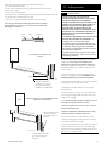
Connections copper tails
Gas Supply - 22mm
Central Heating Flow - 22mm
Central Heating Return - 22mm
Cold Water Mains Inlet - 15mm
DHW Flow - 15mm
Pressure Relief Discharge - 15mm
Temperatures
C.H. Flow Temp (adjustable)
25°C to 80°C max (± 5°C)
D.H.W. Flow Temp (adjustable)
35°C to 60°C max (± 5°C)
dependent upon flow rate
NO
x
Class 5
Heat Input CH (Net) Max Min
24 model kW 20.5 7
28 model kW 24.7 9
33 model kW 28.9 9.7
40 model kW 32.8 9.9
Heat Output CH (Non-Condensing)
Max Min
24 model kW 20 6.8
28 model kW 24 8.7
33 model kW 28 9.4
40 model kW 32 9.6
Electrical Supply 230V~ 50H
z
(Appliance must be connected to an
earthed supply)
Power Consumption
155W (24, 28) 160W (33 & 40)
Electrical Protection
IPX0D (with timer)
IPX5D (without timer)
Internal Fuse Rating F2L
Appliance Category CAT I
2H
Inlet Pressure (Natural Gas - G20)
mbar 20
Injector (Natural Gas - G20)
7.5mm (24 & 28) 12mm (33 & 40)
Appliance Type C
13
C
33
C
53
Heat Output CH (Condensing)
Max Min
24 model kW 21 7.4
28 model kW 25.9 9.5
33 model kW 30.3 10.2
40 model kW 34.4 12.1
Heat Input DHW (Net) Max
24 model kW 24.7
28 model kW 28.9
33 model kW 34
40 model kW 41.2
Heat Output DHW Max
24 model kW 24
28 model kW 28
33 model kW 33
40 model kW 40
Max Gas Rate (Natural Gas - G20)
(After 10 mins)
24 model m
3
/h 2.61
28 model m
3
/h 3.1
33 model m
3
/h 3.6
40 model m
3
/h 4.36
Condensate Drain
To accept 21.5mm (
3
/
4
in) plastic waste pipe
Heat Input CH (Gross) Max Min
24 model kW 22.7 7.8
28 model kW 27.4 10
33 model kW 32.1 10.8
40 model kW 36.4 11
Heat Input DHW (Gross) Max
24 model kW 27.4
28 model kW 32.1
33 model kW 37.7
40 model kW 45.7
External Fuse Rating 3A
The efficiency for all models is 91.1%
This value is used in the UK Government’s Standard
Assessment Procedure (SAP) for energy rating of
dwellings. The test data from which it has been calculated
has been certified by 0087.
SEDBUK Declaration
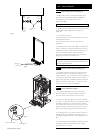
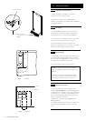
Clearances
Above Casing 200 mm Min
Below Casing 150 mm Min*
Front 450 mm Min(For Servicing)
Front 5 mm Min (In Operation)
L.H. Side 5 mm Min
R.H. Side 5 mm Min (In Operation)
*This is MINIMUM recommended dimension. Greater
clearance will aid installation and maintenance.
NOTE: All data in this section are nominal values
and subject to normal production tolerances.
IMPORTANT: Where Low Flow Taps or Fittings are
intended to be used in the DHW system connected it is
strongly recommended that the DHW flow rate DOES
NOT fall below 2.5l/min. This will ensure reliable
operation of the DHW function.