


27
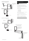
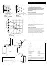
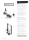
9.0 Plume Displacement
© Baxi Heating UK Ltd 2012
Concentric 60/100 Flue
60Ø Exhaust
X
Y
Fig. 26
2
0
2
4
6
8
10
12
14
60 Ø Exhaust (metres) X
Concentric 60/100 Flue (metres) Y
0
16
1
34 65798
24
28/33/40
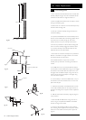
Fig. 27
2
0
2
4
6
8
10
12
14
60 Ø Exhaust (metres) X
Concentric 60/100 Flue (metres) Y
0
16
1
34 65798
24
28/33/40
2
0
2
4
6
8
10
12
14
60 Ø Exhaust (metres) X
Concentric 60/100 Flue (metres) Y
0
16
1
34 65798
24
28/33/40
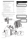
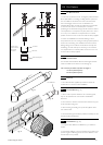
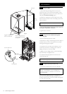
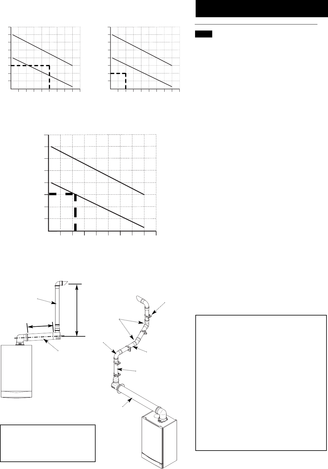
Flue Length - Worked Example
Potterton Titanium 33
In Fig. 27 opposite an additional 93° bend and pair of 45°
elbows have been included in the 60Ø exhaust.
Also 3 straight extension pieces have been used.
To calculate total length:-
Length of 60Ø supplied in kit = 1 metre
3 x 1 metre Extensions = 3 metres
1 x 93° Elbow = 1 metre
2 x 45° Elbow = 1 metre (0.5 metres each)
Total 60Ø = 6 metres
After consulting the table in Example 3 it can be determined
that the concentric flue could be up to approximately 2.3
metres long.
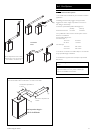
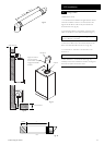
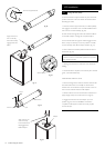
Concentric Flue
Support
Bracket
45° Elbow
93° Elbow
1 metre Extension
1 metre supplied in kit
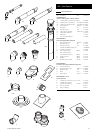
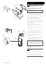
Additional Accessories
A - 93° Elbow 5121369
B - 45° Elbow (Pair) 5121370
C - 1 metre 60Ø Extension 5121368
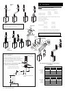
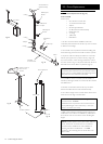
9.2 Determining Permissible Lengths
In the graph the solid line diagonal represents the
relationship between the concentric flue assembly (and any
extensions) and the 60Ø exhaust (and any extensions or
additional bends).
Example 1 - Not Permissible
If, for instance, a concentric length of 5 metres was required
and the 60Ø exhaust needed to be 6 metres the graph
shows that this combination would NOT be permissible as
the intersection point would be above the solid diagonal line.
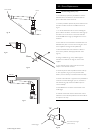
Example 2 - Flue Lengths OK
Where both lengths have been determined they can be
applied to the graph to check that the installation is
permissible. For example, if it was known that 2 metres of
concentric flue and 4 metres of 60Ø exhaust were required,
the values could be applied to the graph as shown in
Example 2.. As the point of intersection of the dotted lines is
below the solid diagonal line, the combination of lengths is
shown to be acceptable.
Example 3 - Flue Lengths OK
In the example shown in Fig. 4 assume that the concentric
part of the flue needs to be 2.3 metres long. Find the
position of ‘2.3’ on the horizontal axis of the graph and then
project upwards to the solid diagonal line. This is represented
by the vertical thick dotted line. Where this dotted line
intersects with the solid diagonal line on the graph, project
across to the vertical axis. As can be seen this corresponds
with 6 metres. Therefore, the total equivalent length of the
60Ø exhaust can be up to 6 metres. Any bend equivalences
must be accounted for i.e. 93° bends are equal to 1 metre,
each 45° bend to 0.5 metres.
Example 1
Flue Lengths - Not Permissible
Example 2
Flue Lengths - OK
Example 3
Flue Lengths - OK