


47
14.0 Changing Components
© Baxi Heating UK Ltd 2012
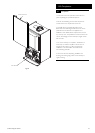
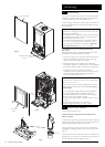
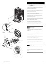
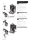
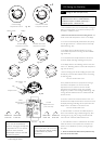
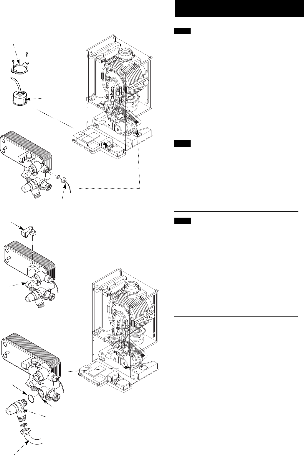
14.17 Pressure Gauge (Figs. 90 & 91)
1. Drain the boiler primary circuit and undo the nut on the
pressure gauge capillary.
2. Undo the screws securing the gauge retaining bracket.
3. Remove the bracket and gauge assembly. Depress the
barbs on the side of the gauge and remove the retaining
bracket.
4. Examine the sealing washer, replace if necessary.
5. Reassemble in reverse order.
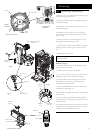
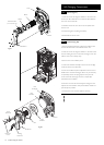
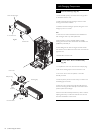
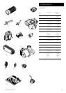
14.18 Hall Effect Sensor (Fig. 92)
1. Ease the sensor upwards off the hydraulic inlet manifold
assembly.
2. Disconnect the electrical plug from the sensor.
3. Connect the plug to the new sensor. Carefully fit the new
sensor to the hydraulic assembly, ensuring it is fully down.
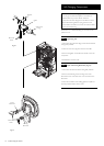
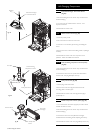
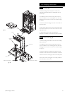
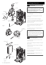
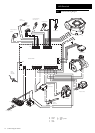
14.19 Pressure Relief Valve (Fig. 93)
1. Drain the boiler primary circuit.
2. Disconnect the discharge pipe from the valve. Using a
suitable hexagon key undo the grub screw sufficiently to
release the valve.
3. Note the orientation of the valve, rotate it and withdraw
it from the manifold.
4. Fit the new valve and ‘O’ ring seal and set to the
previously noted orientation. Reassemble in reverse order.
Pressure Gauge
Pressure Gauge
Capillary
Gauge Retaining
Bracket
Fig. 91
Fig. 90
Pressure Relief Valve
Grub Screw
‘O’ ring seal
Discharge Pipe
Fig. 93
Hall Effect
Sensor
Hydraulic Inlet
Assembly
Fig. 92