


46
14.0 Changing Components
© Baxi Heating UK Ltd 2012
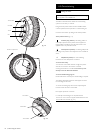
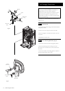
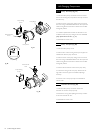
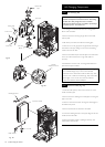
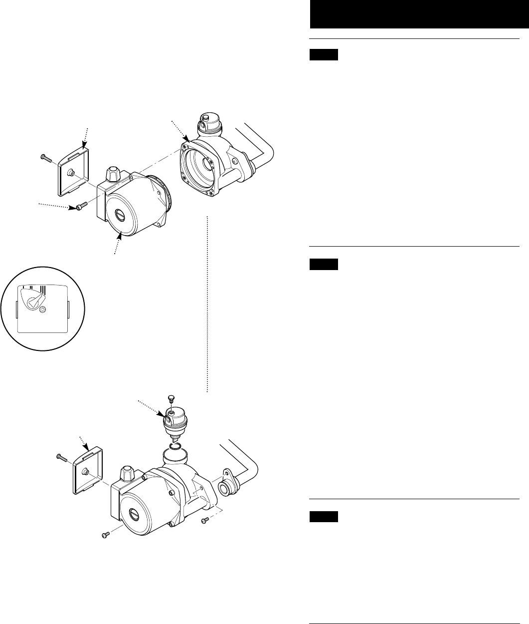
14.14 Pump - Head Only (Fig. 87)
1. Drain the boiler primary circuit and remove the socket
head screws securing the pump head to the body and draw
the head away.
2. Undo the screw on the pump wiring cover and remove
the cover. Using a suitable flat bladed screw driver press the
cable securing levers downwards to release each wire after
noting their position.
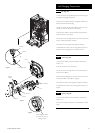
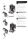
3. A standard replacement Grundfos 15-60 head can now
be fitted. Connect the pump wiring to the new head. The
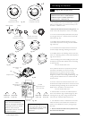
pump speed must be set to 3 (Fig. 88).
4. Reassemble in reverse order.
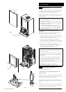
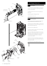
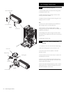
14.15 Pump - Complete (Fig. 88)
1. Drain the boiler primary circuit.
2. Undo the two screws securing the body to the pipe and
manifold and draw the pump forwards.
3. Undo the screw on the pump wiring cover and remove
the cover. Using a suitable flat bladed screw driver press the
cable securing levers downwards to release each wire after
noting their position.
4. Unscrew the automatic air vent from the pump body.
5. Connect the wiring to the new pump. Examine the ‘O’
ring seals on the return pipe and manifold, replacing if
necessary.
6. Fit the air vent to the pump body and reassemble in
reverse order.
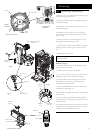
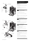
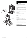
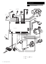
14.16 Automatic Air Vent (Fig. 89)
1. Drain the boiler primary circuit and unscrew the
automatic air vent from the pump body.
2. Examine the ‘O’ ring seal, replacing if necessary, and fit it
to the new automatic air vent.
3. Reassemble in reverse order.
Pump Setting
Socket Headed
Screw
Pump Head
Pump Body
Automatic Air
Vent
Fig. 87
Fig. 89
Fig. 88
Pump Wiring
Cover
Pump Wiring
Cover