


43
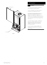
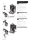
14.0 Changing Components
© Baxi Heating UK Ltd 2012
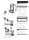
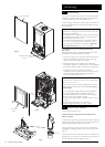
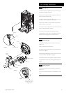
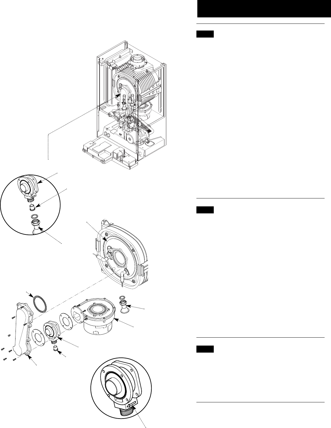
Cover
Gas Inlet
Fan
Venturi
Injector
Collector
Burner
Gasket
When fitting the venturi
ensure that the arrow is
pointing forward
Fig. 78
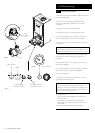
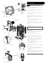
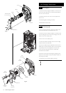
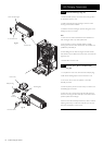
Fig. 79
Gas Inlet Pipe
Venturi
Injector
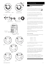
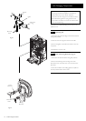
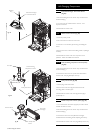
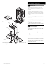
Fig. 80
14.3 Fan (Fig. 79)
1. Undo the nut on the gas inlet pipe to the venturi (Fig. 79)
and pull the sensing pipe off the fan.
2. Disconnect the electrode leads, noting their position and
disconnect the fan electrical plugs.
3. Undo the screws securing the collector to the cover (33
models) or extension piece (24 & 28 models).
4. Remove the collector and fan assembly, being careful to
retain the injector in the venturi.
5. Undo the screws securing the fan to the venturi and fit the
new fan, replacing the seal if necessary.
6. Examine the burner gasket and replace if necessary.
7. Reassemble in reverse order, ensuring that the injector is
in place and the sensing pipe is connected to the fan.
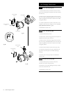
14.4 Venturi (Fig. 78)
1. Remove the collector and fan assembly as described in
section 14.3.
2. Extract the injector from the venturi.
3. Undo the screws securing the fan to the venturi and the
venturi to the collector.
Important: When fitting the new venturi, ensure the arrows
on it’s base point into the collector (Fig. 84).
4. Examine the seals and burner gasket, replace if necessary.
5. Reassemble in reverse order, ensuring that the injector is
in place.
14.5 Injector (Fig. 78)
1. Remove the collector and fan assembly as described in
section 14.3.
2. Extract and replace the injector and reassemble in reverse
order.