


35
10.0 Installation
© Baxi Heating UK Ltd 2012
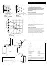
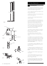
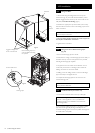
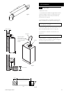
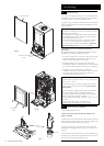
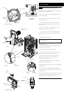
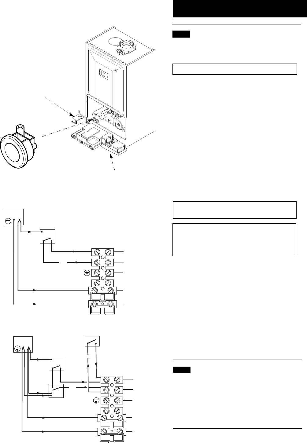
Fig. 56
Fig. 55
Cable Clamp
Facia Panel
Terminal Block Cover
10.8 Making The Electrical Connections
The boiler is fitted with a 1.3m length of 3 core cable. This
can be connected to the fused 3A 230V 50H
Z supply.
NOTE: Both the Live and Neutral connections are fused.
To connect an external control proceed as follows:-
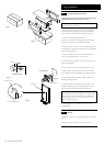
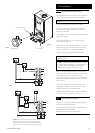
1. Slacken the facia panel securing screws and lift the
outercase panel so that its securing tabs are clear of the
facia. Remove the panel.
2. Completely undo the screws securing the facia panel and
hinge it down (Fig. 55).
3. Undo the terminal block cover securing screw and
remove the cover (Fig. 55).
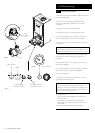
4. Slacken the unused cable clamp on the LH side of the
boiler chassis (Fig. 56). Insert the external control wiring
through the clamp and route it to the terminal block.
5. Refer to the instructions supplied with the control.
IMPORTANT: The room thermostat MUST be suitable
for 230V switching.
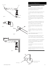
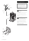
NOTE: An external frost thermostat cannot be used in
conjunction with the integral timer. The integral timer can
be replaced with the blanking plate supplied in the
installation kit, and wiring connected as in Fig. 57.
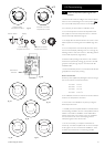
6. Remove the link between terminals 1 & 2. The 230V
supply at terminal 2 must be connected to the thermostat.
The switched output from the thermostat must be
connected to terminal 1 (Fig. 57). If the room thermostat
being used incorporates an anticipator it MUST be wired as
shown in Fig. 57.
7. Ensure that the external control input cable(s) have
sufficient slack to allow the control box to drop down.
Tighten the cable clamp on the boiler chassis.
8. Replace the terminal block cover, routing the external
control input cable(s) through the second cut-out.
10.9 Preliminary Electrical Checks
1. Prior to commissioning the boiler preliminary electrical
system checks should be carried out.
2. These should be performed using a suitable meter, and
include checks for Earth Continuity,
Resistance to Earth, Short Circuit and Polarity.
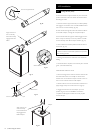
b
br
bk
bk
g/y
1
N
L
2
N
N
L
Room ‘Stat
Fused Spur
230V
Fig. 57
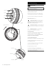
b
br
bk
bk
g/y
1
N
L
Frost
Thermostat
External Clock
2
N
N
L
Room ‘Stat
Fused Spur
230V
230V
NOTE: The 230V switched signal for external controls
(Frost Stat - Room Stat - Timer) must always be taken
from terminal 2 at the boiler. Live, Neutral and Earth to
power these controls must be taken from the Fused Spur.