


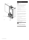
3.0 Appliance Operation
8
© Baxi Heating UK Ltd 2007
NOTE: All delay timers mentioned in 3.1 and 3.2 are
overridden by domestic hot water demand.
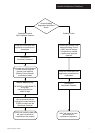
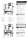
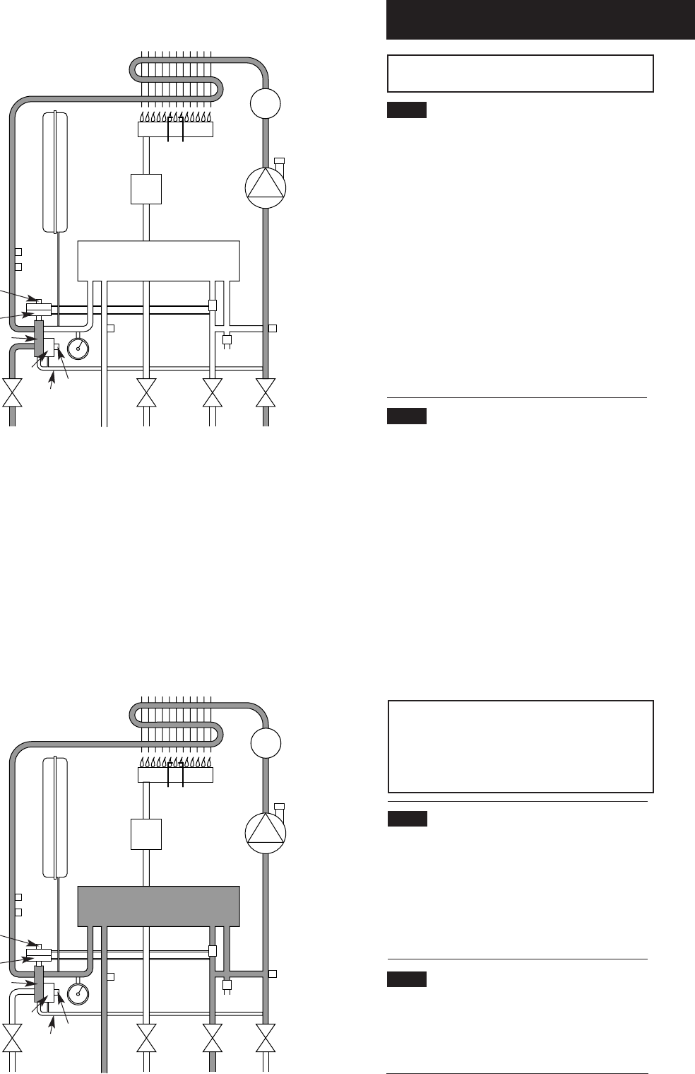
3.1 Central Heating Mode (Fig. 2)
1. With a demand for heating, the pump circulates water
through the primary circuit. At a pre-determined flow
rate the central heating flow switch operates, initiating
the ignition sequence.
2. The main burner ignites at low rate, then the gas valve
controls the gas rate to maintain the heating
temperature measured by the temperature sensor.
3. When the flow temperature exceeds the setting
temperature, a 3 minute delay occurs before the burner
relights automatically (anti-cycling). The pump continues
to run during this period.
4. When the demand is satisfied the burner is
extinguished and the pump continues to run for a
period of 3 minutes (Pump Overrun).
3.2 Domestic Hot Water Mode (Fig. 3)
1. Priority is given to the domestic hot water supply. A
demand at a tap or shower will override any central
heating requirement.
2. The flow of water will operate the DHW flow switch
which requests the 3 way valve to change position. This
will allow the pump to circulate the primary water
through the DHW plate heat exchanger.
3. The burner will light automatically and the
temperature of the domestic hot water is controlled by
the temperature sensor.
4. When the domestic hot water demand ceases the
burner will extinguish and the diverter valve will remain
in the domestic hot water mode, unless there is a
demand for central heating.
IMPORTANT: When the selector switch is in the
‘0’ (Off) position the electrical supply to the boiler
is isolated. The boiler will not operate and the
integral timer (if fitted) will require resetting once
the selector switch is set to either Position (i) or
Position (ii).
3.3 Frost Protection Mode
1. The frost protection mode is integral to the appliance
and functions only with the selector switch (see Section
2.1) in the domestic hot water and central heating
position. If the system temperature falls below 5° C then
the boiler will fire on its minimum setting until a flow
temperature of 30° C is reached. Further protection can
be incorporated by using a system frost thermostat.
3.4 Pump Protection
1. With the selector switch (see Section 2.1) in either
the central heating or central heating and domestic hot
water position the pump will automatically operate for 1
minute in every 24 hours to prevent sticking.
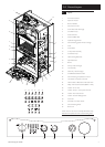
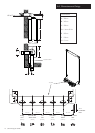
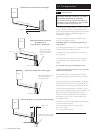
1
2
4
5 6
7
8
9
10
11
1213141516
17
18
19
20
21
22
23
24
25
26
3
1 Primary Heat Exchanger
2 Burner
3 Ignition Electrode
4 Flame Sensing Electrode
5 Gas Valve
6 Pump
7 Automatic Air Vent
8 Plate Heat Exchanger
9 Flow Sensor with Filter
10 Pressure Relief Valve
11 Boiler Drain Point
12 Heating Return
13 Cold Water Inlet On/Off Valve and Filter
14 Gas Inlet
15 Domestic Hot Water Outlet
16 Heating Flow
17 Pressure Gauge
18 Hydraulic Differential Pressure Sensor Microswitch
19 Automatic By-Pass
20 Hydraulic Differential Pressure Sensor
21 Diverter Valve Assembly
22 Domestic Hot Water Flow Priority Assembly
23 Domestic Hot Water Flow Priority Microswitch
24 Safety Thermostat
25 Central Heating Temperature Sensor
26 Expansion Vessel
27 Domestic Hot Water Temperature Sensor
28 Secondary Heat Exchanger
Key
Central Heating Circuit
Domestic Hot Water Circuit
Fig. 3
1
2
4
5 6
7
8
9
10
11
1213141516
17
18
19
20
21
22
23
24
25
26
3
Fig. 2
27
27
28
28