


14.0 Changing Components
44
© Baxi Heating UK Ltd 2007
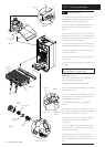
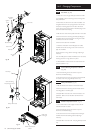
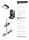
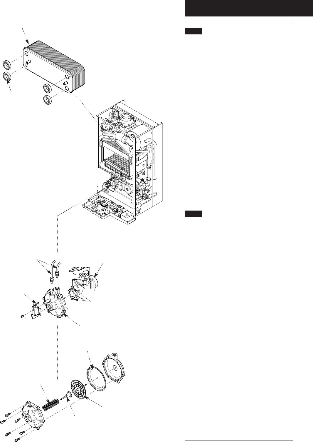
14.21 Plate Heat Exchanger (Fig. 67)
1. Drain the primary circuit.
2. While supporting the heat exchanger undo the
screws securing it to the brass manifolds.
3. Withdraw the heat exchanger upwards and to the
left of the gas valve, taking care not to damage any
wires or controls.
Seals
4. There are four rubber seals between the manifolds
and heat exchanger which may need replacement.
5. Ease the seals out of the manifold. Replace carefully,
ensuring that the seal is inserted into the manifold
parallel and pushed fully in.
6. When fitting the new heat exchanger note that the
left hand location stud is offset towards the centre
more than the right hand one.
7. Reassemble in reverse order.
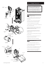
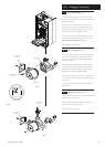
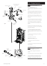
14.22 Diverter Valve Assembly
(Figs. 82 & 83)
The diverter valve assembly comprises of a central
heating pressure differential valve and a domestic hot
water pressure differential valve. These are connected
to a manifold which is joined to the plate heat
exchanger.
DHW Pressure Differential Valve (Fig. 83)
1. Drain the primary circuit.
2. Undo the screw securing the microswitch bracket to
the valve (Fig. 82).
3. Disconnect the two sensing pipes and slacken the
grub screws securing the valve to the diverter manifold.
4. Draw the valve away from the diverter manifold. The
valve may now be replaced or split to examine the
diaphragm.
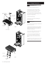
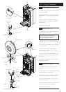
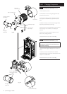
5. To examine the diaphragm hold the valve body
securely and carefully remove the six screws. The
diaphragm spring will force apart the two halves of the
valve.
6. Remove the plastic disc and pushrod assembly.
Carefully examine the diaphragm and replace it if there
is any damage.
7. Reassemble in reverse order.
Plate Heat Exchanger
Rubber Seal
DHW Pressure
Differential Valve
Microswitch
Bracket
Grub Screws
Diverter Manifold
Sensing Pipes
Plastic Disc
Pushrod
Diaphragm
Spring
Diaphragm
Fig. 81
Fig. 82
Fig. 83