


10.0 Installation
27
© Baxi Heating UK Ltd 2007
10.1 Initial Preparation
The gas supply, gas type and pressure must be
checked for suitability before connection (see Section
7.4).
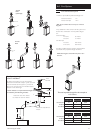
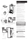
1. After considering the site requirements
(see Section 7.0) position the fixing template on the
wall ensuring it is level both horizontally and vertically.
2. Mark the position of the two most suitable fixing slots
for the wall plate and boiler lower fixing holes. It is
preferable to use the horizontal fixing slots.
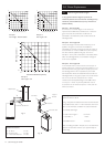
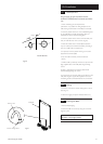
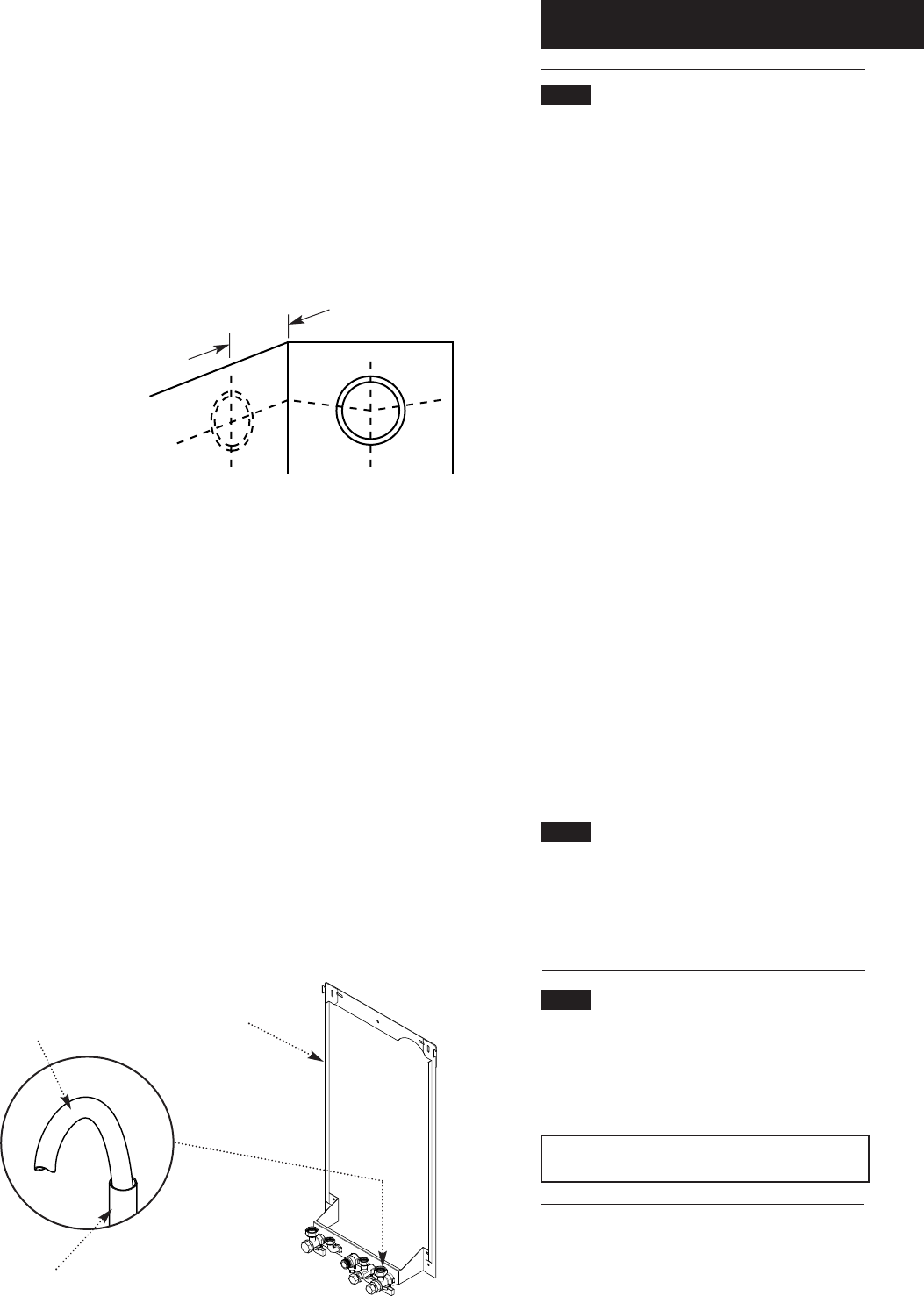
3. Mark the position of the centre of the flue hole (rear
exit). For side flue exit, mark as shown (Fig. 30).
4. Note the shaded area on the template. Pipework
may be routed upwards behind the boiler, providing it
does not conflict with the shaded area.
5. If required, mark the position of the gas and water
pipes. Remove the template.
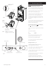
6. Cut the hole for the flue (minimum diameter
116mm).
7. Drill the wall as previously marked to accept the wall
plugs supplied. Secure the wall plate using the fixing
screws.
8. Using a spirit level ensure that the plate is level
before finally tightening the screws.
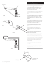
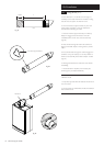
9. Connect the gas and water pipes to the valves on the
wall plate using the copper tails supplied. Ensure that
the sealing washers are fitted between the connections.
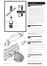
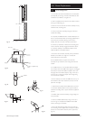
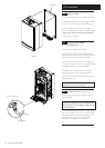
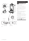
10.2 Flushing
1. Connect a tube to the central heating flow or return
pipe (Fig. 31).
2. Flush thoroughly (see System Details, Section 6.2).
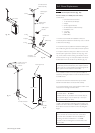
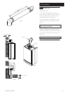
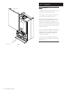
10.3 Preparing The Boiler
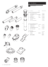
1. Remove all packaging.
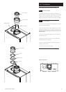
2. Stand the boiler on its base by using the rear lower
edge as a pivot.
NOTE: A small amount of water may drain from
the boiler in the upright position.
Fig. 30
Fig. 31
190mm
For Side Flue Exit
Central Heating Return
Flushing Tube
Wall Plate