


10.0 Installation
28
© Baxi Heating UK Ltd 2007
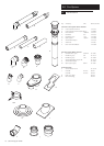
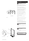
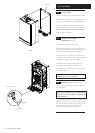
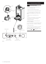
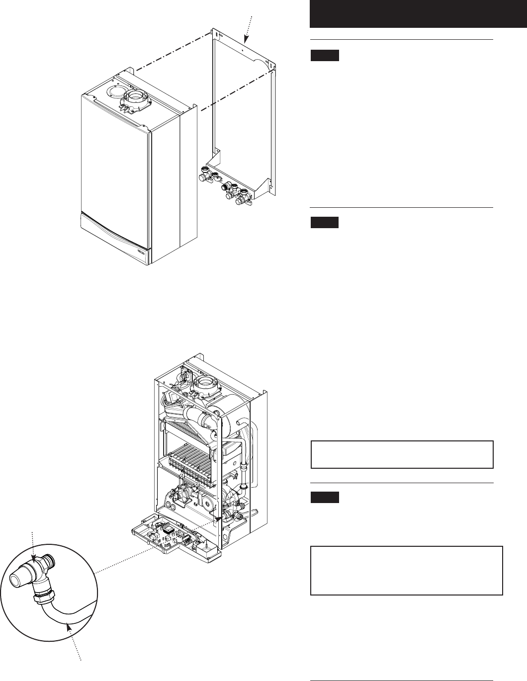
10.4 Fitting The Boiler
1. Remove the sealing caps from the boiler connections.
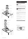
2. Lift the boiler using the lower edges. Engage the slots
at the top rear of the boiler on the wall plate (Fig. 32).
3. Insert the sealing washers between the valves and
pipes on the wall plate and the boiler connections. The
rubber washers must be used on the gas connection.
4. Tighten all the connections.
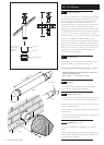
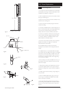
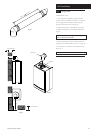
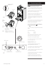
10.5 Fitting the Pressure Relief
Discharge Pipe (Fig. 33)
1. Remove the discharge pipe from the kit.
2. Determine the routing of the discharge pipe in the
vicinity of the boiler. Make up as much of the pipework as
is practical, including the discharge pipe supplied.
3. The pipework must be at least 15mm diameter and
run continuously downwards to a discharge point outside
the building. See section 6.7 for further details.
4. Utilising one of the sealing washers, connect the
discharge pipe to the adaptor and tighten the nut.
5. Complete the discharge pipework and route it to the
outside discharge point.
IMPORTANT: Make all soldered joints before
connecting to the pressure relief valve.
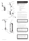
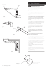
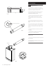
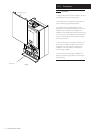
10.6 Condensate Drain (see section 7.6)
1. Connect the condensate drain using the 1” BSP nut
and seal supplied.
Ensure the discharge of condensate complies with any
national or local regulations in force (see British Gas
“Guidance Notes for the Installation of Domestic Gas
Condensing Boilers”.
2. The condensate outlet terminates in a 1” BSP nut and
seal for the connection of 21.5mm (
3
/
4
in) plastic overflow
pipe which should generally discharge internally into the
household drainage system. If this is not possible,
discharge into an outside drain is acceptable.
Fig. 33
Fig. 32
Pressure Relief Valve
Wall Plate
Discharge Pipe