


14.0 Changing Components
42
© Baxi Heating UK Ltd 2007
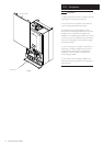
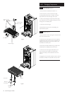
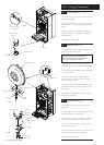
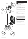
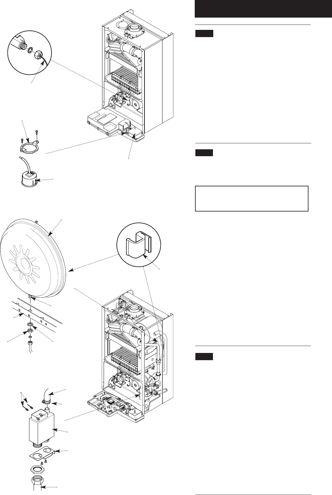
14.15 Pressure Gauge (Figs. 74 & 75)
1. Drain the primary circuit and undo the nut on the
pressure gauge capillary.
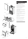
2. Remove the timer cover and ease the timer wiring
aside. Undo the screws securing the gauge retaining
bracket.
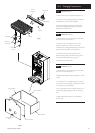
3. Remove the bracket and gauge assembly. Depress
the barbs on the side of the gauge and remove the
retaining bracket.
4. Reassemble in reverse order.
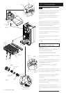
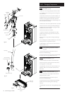
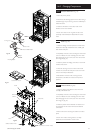
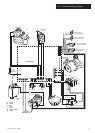
14.16
Expansion Vessel (Fig. 76)
1. To replace the expansion vessel it is necessary to
remove the boiler from the wall.
Note: Alternatively a vessel of equivalent
capacity can be fitted on the system return
pipe as close as possible to the boiler.
2. Drain the system and undo all gas, water and
condensate drain connections. Remove the flue elbow.
3. Lift the boiler off the wall plate and lay it on it’s side
on a clean flat surface.
4. Undo the nut on the vessel outlet spigot, and
remove the locknut and spring washer securing the
spigot to the boiler chassis.
5. Undo the screws and remove the appliance upper
cross member. Slide the expansion vessel out of the
retaining clips.
6. Reassemble in reverse order. Fully recommission
the appliance and system.
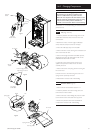
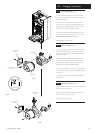
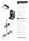
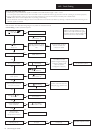
14.17 Condensate Trap (Fig. 77)
1. Disconnect the two sensing wires from the trap
connections.
2. Squeeze together the wire spring clip to release and
ease the inlet pipe from the trap spigot.
3. Undo the nut securing the condensate drain pipe to
the trap. Disconnect the pipe and sealing washer.
4. From underneath the boiler remove the screws
securing the trap bracket.
5. Remove the trap and bracket from the boiler. Undo
the locknut securing the trap to the bracket.
6. Reassemble in reverse order.
Pressure Gauge
Timer Cover
Pressure Gauge
Capillary
Gauge Retaining
Bracket
Expansion Vessel
Retaining Clip
Vessel Outlet Spigot
Boiler Chassis
Lock Nut
Spring
Washer
Fig. 74
Fig. 75
Fig. 76
Inlet Pipe
Sensing Wires
Condensate
Trap
Wire Spring
Clip
Bracket
Condensate
Drain Pipe
Fig. 77