


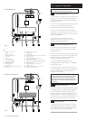
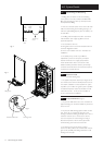
6.0 System Details
12
© Baxi Heating UK Ltd 2007
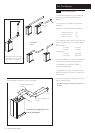
6.5 System Filling and Pressurising
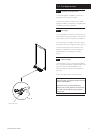
1. A filling point connection on the central heating
return pipework must be provided to facilitate initial
filling and pressurising and also any subsequent water
loss replacement/refilling.
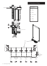
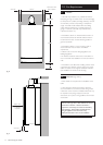
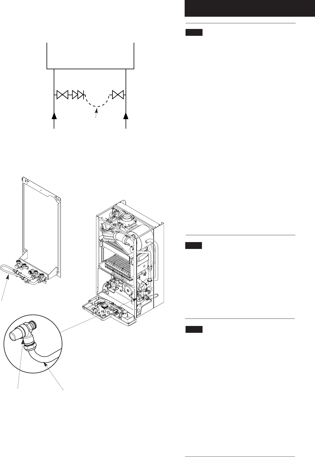
2. There are connection points on the mains cold water
inlet and central heating return isolating taps Fig. 5) to
which the optional filling loop kit (Part No. 248221) can
be assembled.
3. The filling method adopted must be in accordance
with all relevant water supply regulations and use
approved equipment.
4. Your attention is drawn to,
for GB: guidance G24.2 and recommendation R24.2 of
the Water Regulations Guide.
for IE: the current edition of I.S. 813. “Domestic Gas
Installations”.
5. The sealed primary circuits may be filled or
replenished by means of a temporary connection
between the circuit and a supply pipe provided a
‘Listed’ double check valve or some other no less
effective backflow prevention device is permanently
connected at the inlet to the circuit and the temporary
connection is removed after use.
6.6 Expansion Vessel
(Central Heating only)
1. The appliance expansion vessel is pre-charged to 0.5
bar. Therefore, the minimum cold fill pressure is 0.5 bar.
The vessel is suitable for correct operation for system
capacities up to 125 litres. For greater system capacities
an additional expansion vessel must be fitted. For GB
refer to BS 7074 Pt 1. For IE, the current edition of
I.S. 813 “Domestic Gas Installations”.
6.7
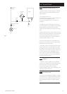
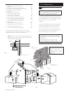
Pressure Relief Valve (Fig. 6)
1. The pressure relief valve is set at 3 bar, therefore all
pipework, fittings, etc. should be suitable for pressures in
excess of 3 bar.
2. The pressure relief discharge pipe should be not less
than 15mm dia, run continuously downward, and
discharge outside the building, preferably over a drain. It
should be routed in such a manner that no hazard
occurs to occupants or causes damage to wiring or
electrical components. The end of the pipe should
terminate facing down and towards the wall.
3. The discharge must not be above a window,
entrance or other public access. Consideration must be
given to the possibility that boiling water/steam could
discharge from the pipe.
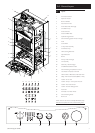
Fig. 4
Fig. 6
Stop
Valve
Double
Check
Valve
DHW
Mains
Inlet
CH
Return
Temporary
Hose
Pressure Relief Valve Discharge Pipe
Filling Loop
Fig. 5
Stop
Valve