


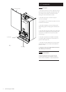
7.0 Site Requirements
14
© Baxi Heating UK Ltd 2007
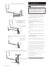
7.1 Location
1. The boiler may be fitted to any suitable wall with the
flue passing through an outside wall or roof and discharging
to atmosphere in a position permitting satisfactory removal
of combustion products and providing an adequate air
supply. The boiler should be fitted within the building
unless otherwise protected by a suitable enclosure i.e.
garage or outhouse. (The boiler may be fitted inside a
cupboard-see Section 7.3).
2. If the boiler is sited in an unheated enclosure then it is
recommended to leave the ON/OFF Selector Switch in
the domestic hot water and central heating position to
give frost protection.
3. If the boiler is fitted in a room containing a bath or
shower reference must be made to the relevant
requirements.
In GB this is the current I.E.E. Wiring Regulations and
Building Regulations.
In IE reference should be made to the current edition of
I.S. 813 “Domestic Gas Installations” and the current ETCI
rules.
4. If the boiler is to be fitted into a building of timber frame
construction then reference must be made to the current
edition of Institute of Gas Engineers Publication IGE/UP/7
(Gas Installations in Timber Framed Housing).
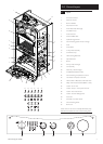
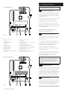
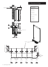
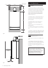
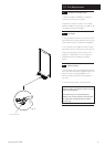
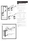
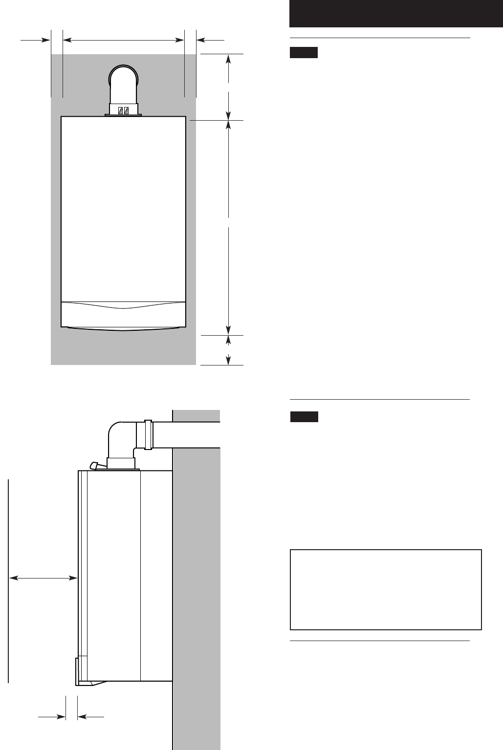
7.2 Clearances (Figs. 8 & 9)
1. A flat vertical area is required for the installation of the
boiler.
2. These dimensions include the necessary clearances
around the boiler for case removal, access during routine
maintenance and air movement. Additional clearances may
be required for the passage of pipes around local
obstructions such as joists running parallel to the front face
of the boiler.
* NOTE: The boiler can be operated with a clearance
of 5mm at the right. This is also sufficient for routine
maintenance. However a clearance of 20mm is
required if it is necessary to remove the secondary
heat exchanger. This should be considered when
siting the appliance and in the event of any
subsequent alteration in the area of installation.
200mm Min
780mm
450mm
200mm Min
20mm/5mm Min
See * NOTE:
5mm Min
5mm Min
450mm Min
For Servicing
Purposes
Fig. 8
Fig. 9
In Operation