


14.0 Changing Components
45
© Baxi Heating UK Ltd 2007
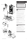
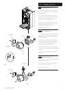
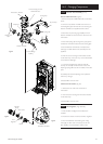
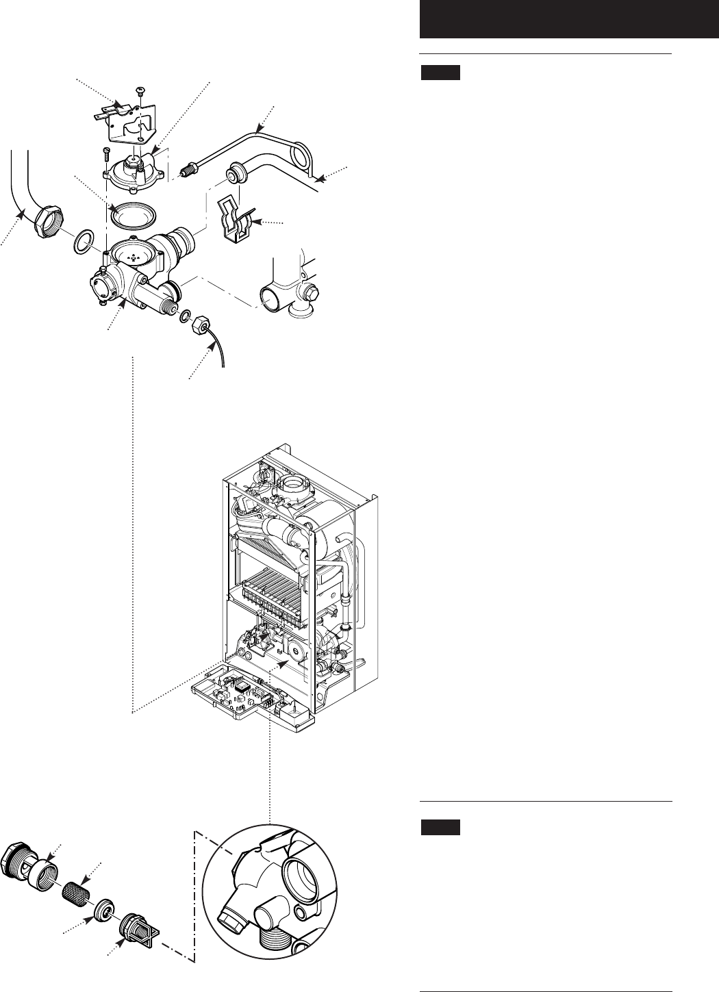
14.22 Diverter Valve Assembly (Cont)
Pressure Differential Valve (Fig. 84)
1. Remove the pressure differential valve as described
above.
2. From the brass diverter manifold undo the nut on
the heating flow pipe. Remove the screw securing the
diverter manifold to the appliance lower bracket.
3. Disconnect the pressure gauge capillary from the
diverter manifold and remove the two wires from the
microswitch.
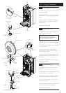
4. Prise off the spring clip securing the by-pass pipe to
the diverter manifold and disconnect the sensing pipe.
5. Ease the diverter manifold out of the plate heat
exchanger manifold. Remove the assembly from the
appliance.
6. Undo the screw securing the microswitch bracket
to the valve body. The sensor may now be dismantled
to examine the diaphragm.
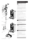
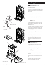
7. To examine the diaphragm hold the assembly
securely and carefully remove the four screws. The
diaphragm spring will force the two halves of the valve
apart.
8. Carefully examine the diaphragm and replace it if
there is any damage.
9. Reassemble in reverse order.
CH Pressure Microswitch (Fig. 84)
1. Remove the two wires from the Pressure
microswitch.
2. Undo the screw securing the microswitch bracket
to the valve body.
3. Reassemble in reverse order.
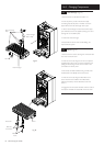
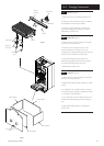
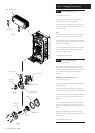
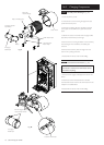
14.23 Flow Regulator (Figs. 85 & 86)
1. Undo the filter cartridge from the inlet/return
manifold.
2. Unscrew the venturi and remove the flow regulator.
3. Check the cleanliness of the filter gauze, rinsing
thoroughly in clean water as necessary. Fit the new
flow regulator and reassemble in reverse order.
Pressure Gauge
Capillary
Heating Flow
Pipe
Spring Clip
By-pass Pipe
Sensing Pipe
Diaphragm
Diverter Manifold
Microswitch / Bracket
Central Heating Pressure
Differential Valve
Fig. 84
Cartridge
Body
Filter Gauze
Flow
Regulator
Venturi
Inlet/Return Manifold
Fig. 85
Fig. 86