


14.0 Changing Components
40
© Baxi Heating UK Ltd 2007
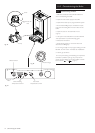
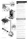
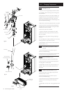
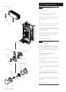
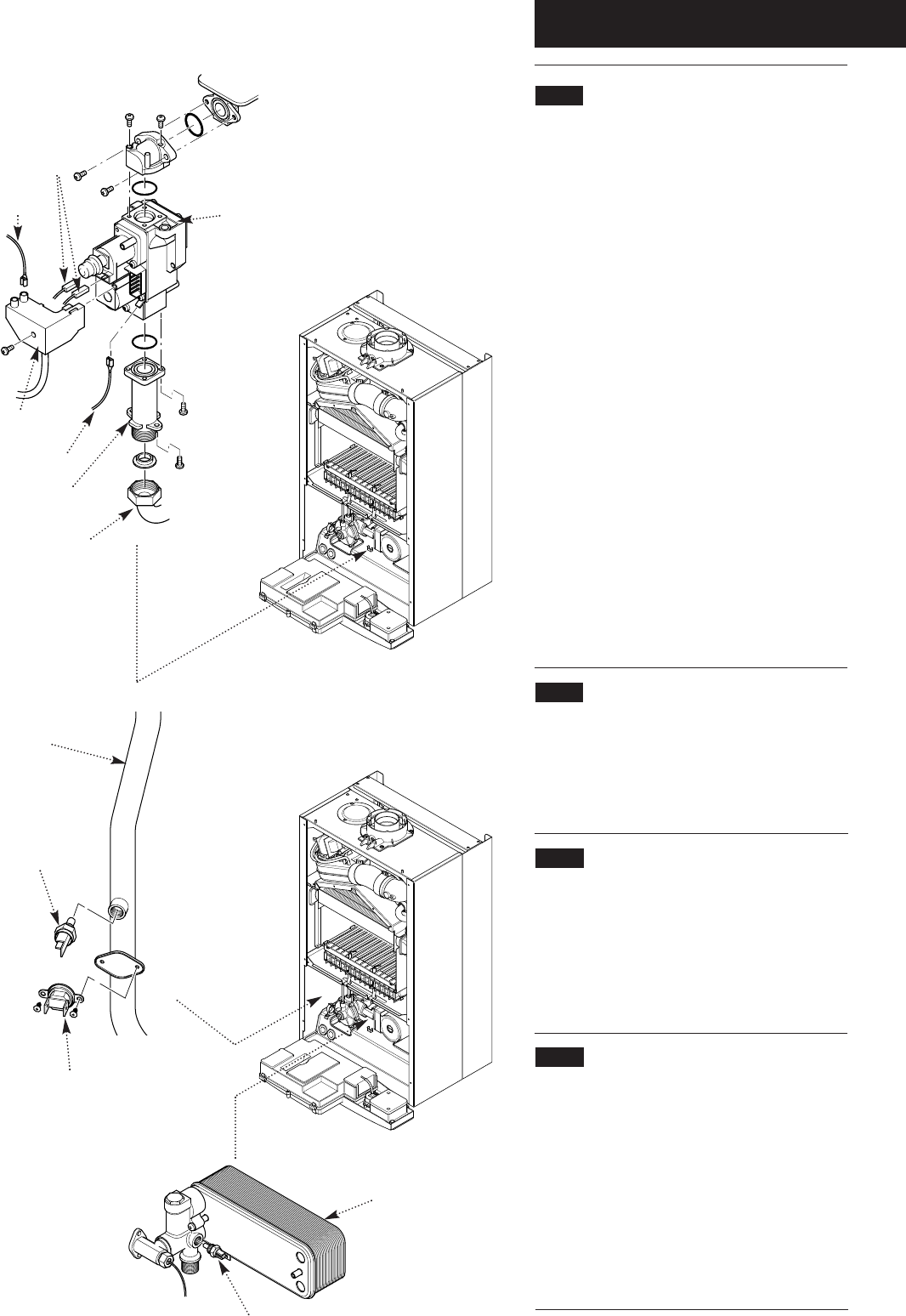
14.8 Gas Valve (Fig. 68)
1. Undo the nut on the gas feed pipe under the boiler.
2. Completely undo the securing screws and hinge the
facia panel down.
3. Disconnect the wires from the valve modulator and
the ignition lead from the spark generator. Disconnect
the pressure sensing pipe from the valve. Undo the
screw securing the spark generator electrical plug to the
valve and disconnect the plug.
4. Pull the earth wire off the spade terminal on the valve.
5. Remove the screws securing the inlet pipe flange to
the boiler bottom panel and those securing the outlet
manifold to the burner manifold.
6. Remove the valve from the boiler.
7. Note the orientation of the inlet pipe and outlet
manifold. Undo the securing screws and remove the
pipe and manifold.
8. Examine the ‘O’ ring seals for damage, replacing as
necessary.
9. Fit the inlet pipe and outlet manifold to the new valve,
ensuring that the ‘O’ ring seals are in place.
10. Reassemble in reverse order and check the burner
pressure (Section 11.2).
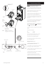
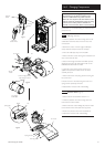
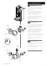
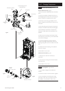
14.9 Central Heating Temperature Sensor
(Fig. 69)
1. Ease the retaining tab on the sensor away and
disconnect the electrical plug.
2. Unscrew the sensor from it’s pocket and reassemble
in reverse order. The plug will only fit one way.
14.10 Safety Thermostat (Fig. 69)
1. Pull the electrical connections off the thermostat.
2. Remove the screws securing the thermostat to the
mounting plate on the flow pipe.
3. Reassemble in reverse order. The thermostat is not
polarised - either wire can fit either terminal on the
thermostat.
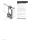
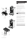
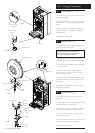
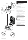
14.11 DHW Temperature Sensor (Fig. 70)
1. Turn off the mains water supply and draw off the
residual domestic hot water.
2. Ease the retaining tab on the sensor away and
disconnect the electrical plug.
3. Unscrew the sensor from the plate heat exchanger
manifold. Examine the sealing washer,replacing if
necessary.
4. Reassemble in reverse order. The plug will only fit one
way.
Gas Valve
Inlet Pipe
Gas Feed
Pipe
Electrical Plug
Central Heating
Temperature Sensor
Safety Thermostat
Flow Pipe
Fig. 68
Fig. 69
DHW Temperature
Sensor
Fig. 70
Plate Heat
Exchanger
Modulator
Wires
Ignition
Lead
Earth Wire