


Pelco Manual C557M (10/99) 9
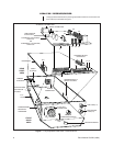
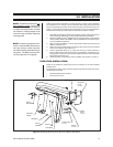
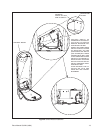
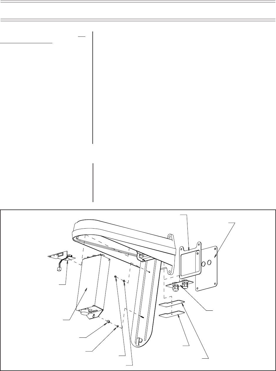
Figure 2. Mounting Receiver/Driver Box Into LWM41 Wall Mount
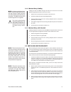
3.0 INSTALLATION
LRD41 receiver/driver installation is usually just part of a larger system installation
that includes the prior routing of power and other cable wiring (Coax, Alarm and
Aux) to the openings where they will be used. To install a receiver/driver at any one
location, perform the following steps (the step sequence is only summarized below;
“fleshed” out instructions for each step are referred to by section number):
1. Assemble small hardware items such as glands, gasket, plates and receiver/
driver anchoring hardware that will be needed during the installation.
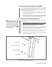
2. Mount the LWM41 (Legacy
®
Wall Mount) into which the LRD41 receiver/driver
will be installed. Refer to the LWM41 manual (C283M) that accompanied your
unit for installation instructions.
3. After mounting the LWM41, route the appropriate cables and wiring into the
LWM41 (see Section 3.1).
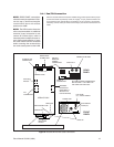
4. Attach input power cable leads to the bracket switch and mount the bracket
switch on the LWM41 (see Section 3.2 ).
5. Connect applicable cables, (e.g., Coax) and wires (e.g., Alarm and Aux) to
their provided external mating connectors (if applicable) in preparation for at-
taching these connectors to their proper mating connectors on the LRD Rear
Panel itself (see Section 3.4 ).
6. Install the LRD41 receiver/driver into the LWM41 (see Section 3.3 and 3.4).
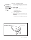
TOOLS FOR INSTALLATION
These will be needed for attaching the power connections to the switch bracket
terminal block.
It is important for cable routing purposes that the steps be followed in their recom-
mended sequential order.
• Small standard-head screwdriver
• 5/16-inch hex wrench
NOTE:
All directional references, un-
less otherwise noted, assume the
mount has been properly installed on
a suitable mounting surface, and that
the installer is looking straight at the
mount from the nose back toward the
mounting plate.
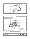
NOTE:
In bottom-entry/gland instal-
lations, install the BNC connectors to
the video out/sync cables only after
the cable has been threaded through
the glands. The BNC connectors will
not fit through the PG-13 glands.
GASKET
SWITCH
BRACKET
RECEIVER/
DRIVER
THUMBNUT
NYLON
WASHER
ANCHOR
SS WASHER
GASKET
(OPTIONAL)
COVER PLATE
(OPTIONAL)
GLAND
PLATE
(OPTIONAL)
BLOCK-OFF
PLATE
(OPTIONAL)