


Pelco Manual C557M (10/99) 15
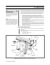
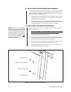
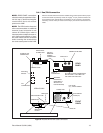
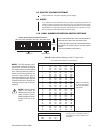
3.4.1 Pan/Tilt Connection
After the receiver/driver box has been installed to the access panel with the proper
connections made as previously noted, the Legacy
®
37-pin, pan/tilt connector can
be connected to the receiver/driver box. With the 37-pin connector, all enclosure,
accessory, camera video (as well as Camera Sync), lens and P/T connections are
made.
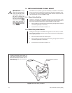
NOTE:
REAR PANEL connections
should be made (as explained in Sec-
tion 3.4, step 1), before mounting the
receiver/driver box to the access
panel on the LWM.
NOTE:
The LRD41 series of receiver/
drivers accommodates an additional
electrical (coax) connection to the
camera for Camera Sync, which is
necessary when multiple cameras re-
quire frame synchronization. If used,
this cable should also be connected
before mounting the receiver/driver
box to the access panel on the LWM.
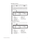
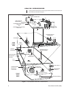
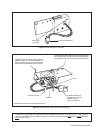
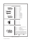
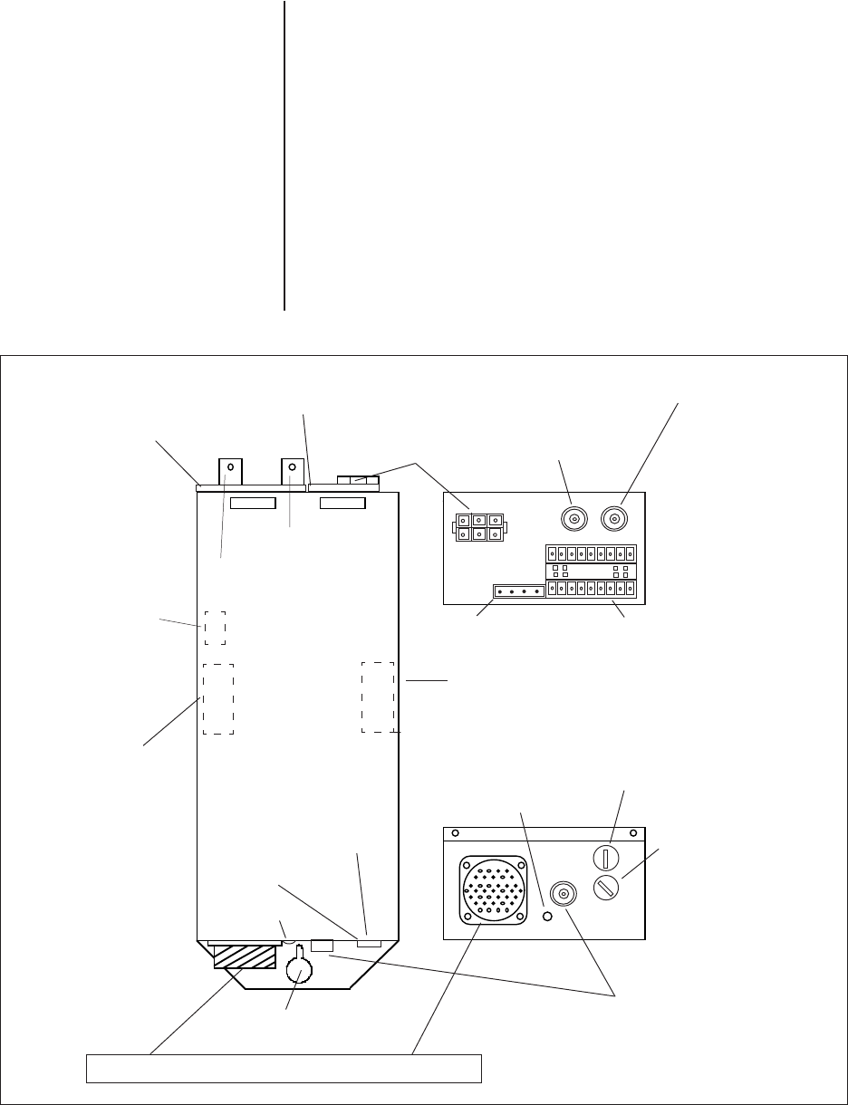
Figure 8. Receiver/Driver Box Cable Connectors
VIDEO OUT
CAMERA SYNC
VIDEO OUT
CAMERA SYNC BNC
LRD41C21/22-*
POWER LED
TLC
CONNECTOR
37-PIN CONNECTOR
MOUNTING
NOTCH
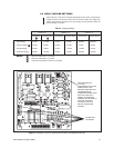
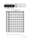
ADDRESS
DIP-SWITCH
(SEE TABLE 2,
SECTION 4.9
FOR SETTINGS)
LRD FUSE
ENCLOSURE FUSE
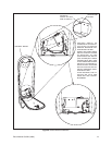
POWER LED
ALARM & AUX
CONNECTOR
RS422 INPUT
CONNECTOR
LRD FUSE
(F1), INPUT POWER
ENCLOSURE
FUSE (F2)
SWITCH
BRACKET
POWER
CONNECTOR
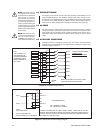
AUX AND ALARM CONNECTORS:
SEE FIGURE 11 OR LABEL ON
LRD UNIT FOR PIN-OUTS.
RS422
CONNECTOR
VIDEO IN
37-PIN CONNECTOR
FRONT
PANEL
REAR
PANEL
LENS POT
ADJUST