


18 Pelco Manual C557M (10/99)
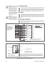
4.3 PREPOSITIONING
The Legacy
®
Pan and Tilt utilizes linear taper precision potentiometers as the
position feedback sensors. This feedback voltage is fed to the receiver’s micro-
controller where it is digitized and stored on nonvolatile memory chips. Each receiver
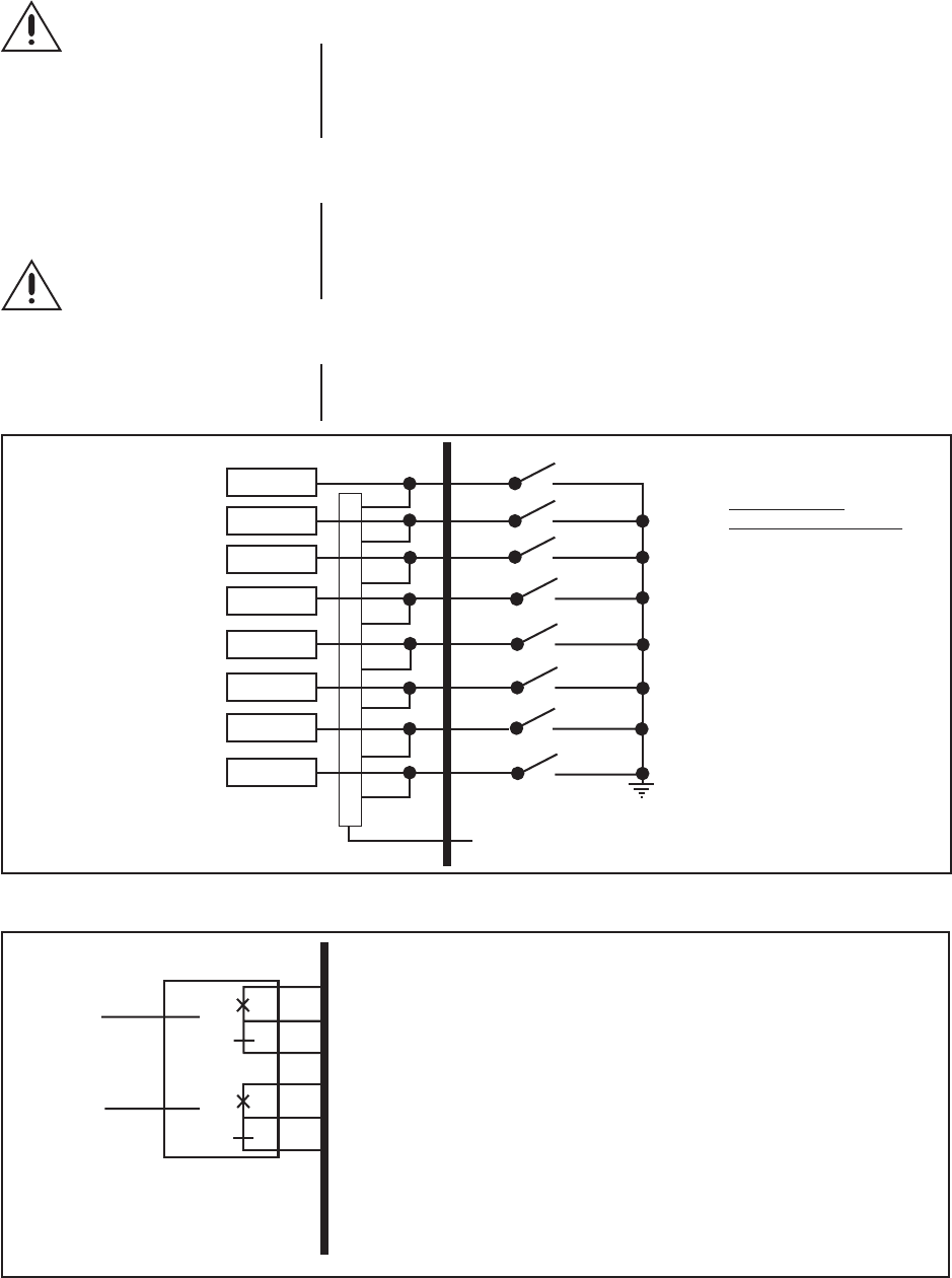
can store up to 64 preset positions for LRD41C models. The first eight presets for
either series are tied to the eight alarm contacts in the receiver (see Figure 10).
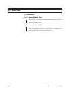
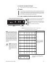
4.4 ALARMS
The LRD41C21/22-* support eight alarm inputs and one alarm output. If multiple
alarms are activated, the receiver will sequence between the alarm presets. Up to
eight presets can be activated by alarm contacts connected to the receiver. Any of
these alarm inputs would activate an external device through an open collector
output.
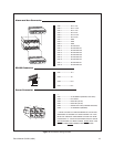
4.5 AUXILIARY FUNCTIONS
The LRD41C21/22-* is capable of operating up to two remotely activated auxiliary
functions. Aux 3 is not available. Aux 4’s logical output is dedicated to wiper control
inside the Legacy
®
enclosure.
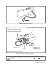
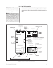
Figure 10. Preposition Alarm Wiring
NOTE:
The Alarm Out sig-
nal (capable of 25 mA sink-
ing maximum) is intended for
logic circuits or other low-
power devices. If you connect
a device that draws more cur-
rent than the maximum al-
lowed, you could destroy the
output circuitry. If you wish to
operate a device that requires
greater current, then interface
it with a relay.
ALM 1
ALM 2
ALM 3
ALM 4
ALM 5
ALM 6
ALM 7
ALM 8
ALARM
OUT
A GND SIGNAL
ACTIVATES AN ALARM
WHEN AN ALARM IN OCCURS, IT WILL
ACTIVATE AN ALARM OUT (GND)
PRESET 1
PRESET 2
PRESET 3
PRESET 4
PRESET 5
PRESET 6
PRESET 7
PRESET 8
LRD
USER SUPPLIED WIRING
18
15
16
13
14
11
12
10
THE ALARMS (1-8)
ARE TIED TO THE
CORRESPONDINGLY
NUMBERED FIRST
EIGHT PRESETS IN
ALL UNITS.
17
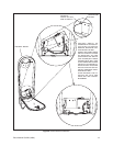
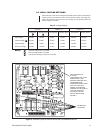
Figure 11. Sample Aux Function Wiring Diagram
AUX 1
AUX 2
AUX 3
(NOT AVAILABLE)
AUX 4 (DEDICATED TO
WIPER CONTROL, ALL MODELS)
CUSTOMER WIRING
NO
NC
AUX OUT
NO
NC
AUX OUT
1
2
3
4
5
6
PIN
OUTPUTS SHOWN ARE IN THEIR “STATIC” STATE. WHEN ANY AUX IS AS-
SERTED, NO’S BECOME NC’S AND VICE VERSA. DEVICES CONNECTED TO
OUTPUT RELAYS SHOULD NOT EXCEED THE SWITCH CONTACT RATING.
THE LIMIT IS 1 AMP @ 24 VDC.
NO = NORMALLY OPEN
NC = NORMALLY CLOSED
NOTE:
Alarm and Aux func-
tions can be enabled through
the use of the LRD41C-
CONNKIT (see Section 7.0
under Optional Accessories).