


10 Pelco Manual C557M (10/99)
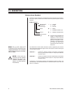
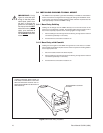
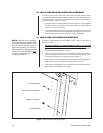
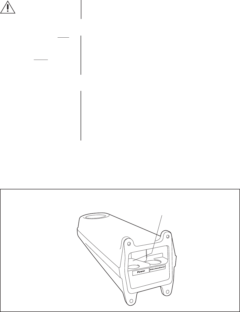
Figure 3. Arm Rear Entry Locations
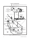
3.1 INSTALLING CABLING TO WALL MOUNT
The LWM41 mount provides a great deal of flexibility in installations. Listed below
are the most common configurations for bringing the cabling into the LWM41 mount.
In each case, note that the supplied gaskets, glands and block-off plates must be
used appropriately to achieve a NEMA 4 rating.
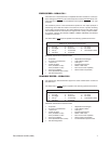
3.1.1 Rear Entry Cabling
Cabling can be brought into the LWM41 directly from a wall into the rear of the
mount arm. In the absence of conduit, the provided gasket must be used to form a
seal. This is especially important when mounting against a rough surface.
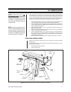
1. Pull the cabling into and through the mount allowing enough slack to make all
connections (preferably 4 to 6 inches).
2. Proceed with the connections in Section 3.2.
3.1.2 Rear Entry with Conduit
Cabling can be brought into the LWM41 through the rear of the mount, in conduit.
The provided conduit block-off plate must be used in conjunction with the gasket to
form an appropriate seal.
1. Secure the cable conduit to the block-off plate.
2. Pull the cabling into and through the mount allowing enough slack to make all
connections (preferably 4 to 6 inches).
3. Proceed with the connections in Section 3.2.
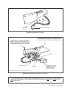
CHASSIS GROUND WIRE (PART OF
THE LWM) IS ATTACHED TO THE LRD
SWITCH BRACKET DURING ITS IN-
STALLATION (REFER TO SECTION 3.2
AND FIGURE 5)
APPROXIMATE LOCATION
OF WIRE
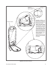
IMPORTANT:
Using
Figure 3, orient the input
wiring so that the power
cable feeds (either from
the wall, or through the
glands on the bottom of
the mount) into the
LEFT
side of the mount, and the
video, sync aux/alarm &
RS422 cables/wires feed
into the
RIGHT
side of the
mount.