


6 Pelco Manual C557M (10/99)
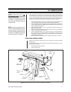
2.0 DESCRIPTION
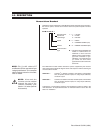
Nomenclature Breakout
Listed below is the relationship of LRD Model numbers discussed in this manual to
the various options, features and functions that those position-specific numbers
represent.
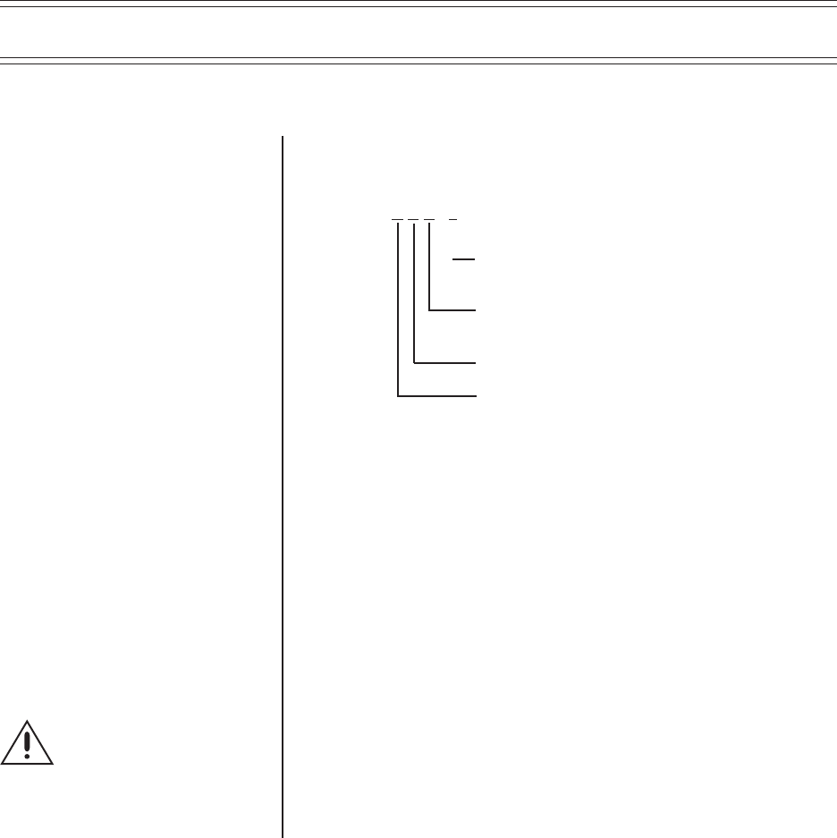
L R D 41 C X X - *
Receiver/Driver * =1=120 VAC
Operational 2 = 24 VAC
Input Voltage 3 = 230 VAC
Speed X = 1 = FIXED
2 = VARIABLE SPEED (VS)
Presets X = 2 = PRESET POSITIONS (PP)
Communication
Type C = Combined–Coax and RS422. All
models of receiver/driver are
hardwired for both Coax and
RS422. Use the communication
type most convenient for your
installation, just remember that
you cannot use both control
types within the same unit at the
same time.
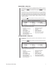
The LRD41Xxx-x model number reflects the options supported by the receiver/
driver. Reference the breakout diagram above and compare it with the following list
of receiver/driver models:
LRD41C21-*: Coaxitron
®
or RS422 controlled, fixed speed, Auto/Random
scan, 64 presets, 8-alarm inputs, two relay output auxiliaries,
one alarm output.
LRD41C22-*: Coaxitron
®
or RS422 controlled, variable speed, Auto/Random
scan, 64 presets, 8-alarm inputs, two relay output auxiliaries,
one alarm output.
A discussion of receiver/driver features and operational functions is listed in the
next subsection. An expanded discussion of individual features occurs after the
section on installation.
NOTE:
The (-*) suffix refers to P/T
and Receiver/Driver operational input
voltage specifications. For a complete
table of voltage values for all models,
refer to Table A.
NOTE:
Alarm and Aux
functions can be enabled
through the use of the
LRD41C-CONNKIT (see
Section 7.0 under Optional
Accessories).