


20 Pelco Manual C557M (10/99)
4.6 AUTO/RANDOM SCAN OPERATION
Auto and random scan can be operated in either of two ways, depending on the
type of control unit you have. One method involves using the Auto/Man switch (or
keys) if your control unit has these functions. The other method involves setting
presets.
Auto/Man Switch – The Random Scan and Auto Scan functions are controlled by
the same momentary switch on the control panel labeled Auto and Man. The first
activation of the switch to the Auto position will put the pan/tilt into Random Scan. In
Random Scan operation, the pan/tilt will travel between the preset limits with a
random scan period of about 2 to 30 seconds, and a random dwell period of be-
tween 2 to 30 seconds.
At the completion of a dwell period, another random scan period is started. The
direction of this scan period is also randomly determined. When a pan limit is reached,
scan direction is reversed automatically.
A second activation of the Auto switch will put the pan/tilt into continuous duty Auto
Scan (limit switch to limit switch). After approximately 1/2 hour of auto scan, the
circuit will reset to random scan. Commanding Auto while in Random mode causes
a shift to Auto mode and starts the 1/2-hour timer. Similarly, commanding Auto
while in Auto mode causes a shift to the Random mode and zeros the 1/2-hour
timer.
Presets – Auto and random scan also can be started by programming presets. The
presets will work only when your system is configured for Extended (32-bit) Coaxitron
mode.
Refer to your controller documentation for programming presets.
Preset 96 stops a scan.
Preset 97 starts random scan.
Preset 99 starts auto scan.
Advantages of Random Scan:
• Because scan direction, scan period and dwell period are unpredictable, un-
authorized activities or intrusions are discouraged.
• Because of the reduced duty cycle, gear train wear, cable fatigue, drive motor
wear and temperature rise are reduced. These factors all contribute to higher
system reliability and increased equipment life.
4.7 TEST LOCAL CONTROL “TLC”
This feature allows you to connect an LRD41TLC Test Local Control (TLC) module
to the receiver/driver to test the control of pan, tilt and lens functions locally. This is
convenient for positioning limit stops, backfocusing, and troubleshooting the instal-
lation. The TLC module also allows positioning of the camera locally.
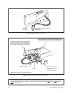
To use the TLC module:
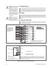
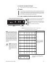
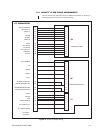
1. Turn receiver OFF and plug the 16-pin connector from the TLC module into
the TLC connector on the receiver/driver (refer to Figure 1). Turn the receiver
ON to activate TLC functions.
2. Hold down the keys on the TLC module to operate the pan, tilt, and camera
functions.
3. Upon completion, detach the TLC; the LRD unit will revert to its previous op-
erational configuration.
NOTE:
The receiver does not have
to be connected to other control
equipment in order for the TLC mod-
ule to work. If the receiver is con-
nected to other control equipment, the
TLC module will override any trans-
mitter control signals from other con-
trol equipment.