


Pelco Manual C557M (10/99) 11
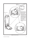
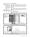
3.1.3 Bottom Entry Cabling
Cabling can enter the LWM41 through the bottom of the mount arm. The cable
glands and gland plate must be used to form a seal.
1. Remove the cover plate from the bottom of the mount arm.
2. Thread the cabling through the glands/gland plate.
3. Feed the cable through the mount, leaving adequate slack for connections
(preferably 4 to 6 inches).
4. Then tighten the glands and secure the gland plate into place on the bottom of
the mount.
5. Proceed with the connections in Section 3.2.
3.1.4 Bottom Entry with Conduit
Cabling contained in conduit can enter the LWM41 through the bottom of the mount
arm. The gland plate (with glands removed) must be used to form a seal.
1. Remove the glands from the gland plate.
2. Secure the conduit to the gland plate.
3. Feed the cable through the mount, leaving adequate slack for connections
(preferably 4 to 6 inches).
4. Secure the gland plate into place on the bottom of the mount.
5. Proceed with the connections in Section 3.2.
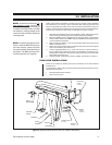
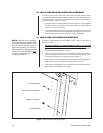
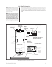
3.2 INSTALLING SWITCH BRACKET
Before installing the switch bracket (see Figure 4) into the LWM41 wall mount, the
power and video cables must be routed through the mount (as explained in Section
3.1), and the power leads need to be connected to the power switch terminal block
on the switch bracket.
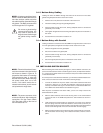
To connect power to the switch terminal block, you will need a small standard screw-
driver, and a 5/16-inch hex wrench. Perform the following step(s):
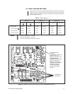
1. Connect the leads from the power cable to the switch bracket terminal block
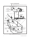
as shown in Figure 5. For 120 VAC and 230 VAC, make sure the ground is
securely connected. Note Figure 3 and be certain to install chassis GND wire
from LWM to the Switch Bracket as indicated in Figure 5.
After the power connections have been made, you are now ready to secure the
Switch Bracket into place.
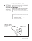
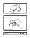
2. With the cable retracted, hook the left securing notch on the switch bracket
over the left tab on the LWM and position the switch bracket as shown in
Figure 6.
3. Hold and press the switch bracket up against the roof of the arm to depress
the bow spring and at the same time rotate the entire switch (as shown), so
that the remaining securing notch located on the right side of the switch bracket
moves toward the right tab on the arm until the notch and tab engage
4. Make sure the tab “clicks” into the securing notch of the bracket for a secure fit.
The fit should be nice and snug, with no lateral movement, once the unit is in
place.
NOTE:
In bottom-entry/gland instal-
lations, install the BNC connectors to
the video out/sync cables only after
the cable has been threaded through
the glands. The BNC connectors will
not fit through the PG-13 glands.
NOTE:
The switch bracket will even-
tually be mounted to the back end of
the mount as shown in Figure 6. To
preposition the bracket for mounting
(after performing step 1), move the
bracket into the arm while extracting
the power cable back out of the
mount. If the cable cannot be re-
tracted in this manner, push it into the
cavity behind the hinge base.
NOTE:
The power connector clicks
and locks into place. After making the
connection, turn the Power Switch
ON. The power LED on the front of
the LRD should be LIT.
Do not use a gland sealing
compound at this time. You
may need to slide the ca-
bling back and forth through
the glands during installa-
tion.