


4 Pelco Manual C557M (10/99)
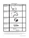
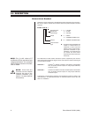
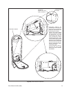
Description Item Qty
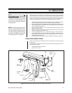
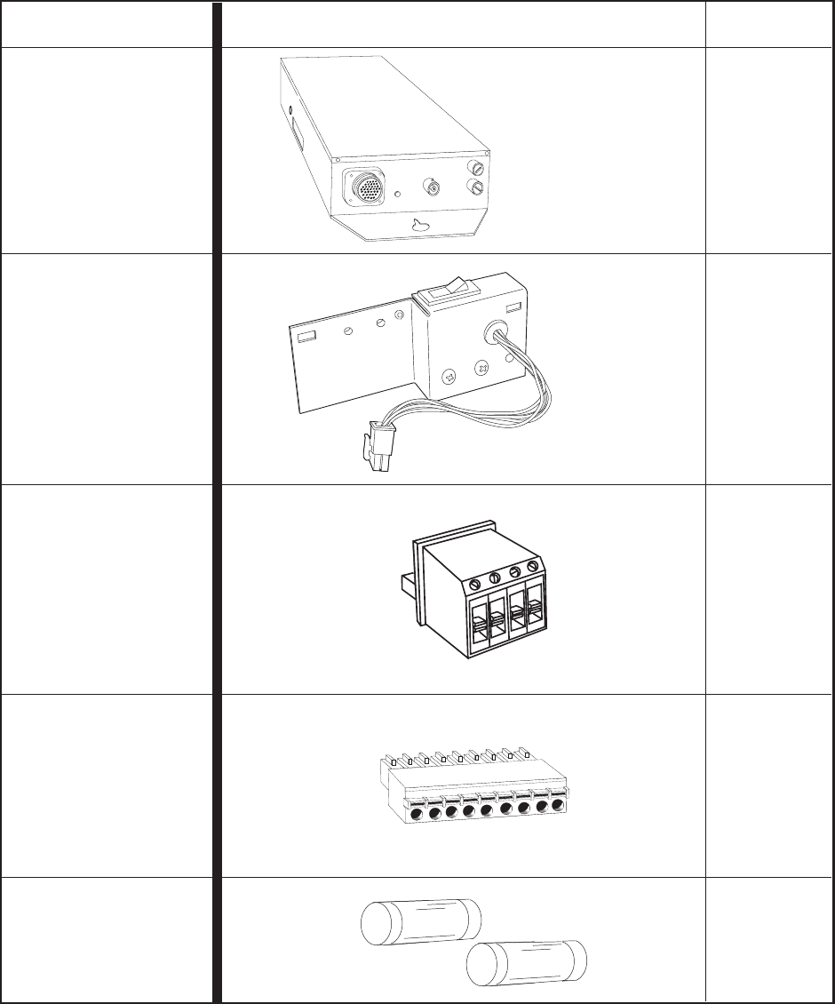
The LRD unit itself–either
the LRD41C21-1,2,3
or the LRD41C22-1,2,3
The switch bracket
(customer installed) used to
bring in power to the LRD
unit
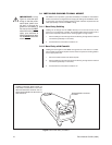
Four position connector for
interfacing with RS422
communication connector
on LRD
9-pin “quick-connect/
disconnect” connector for
interfacing with the AUX/ALM
connector on the LRD
1
1 set of 2
There are two functional
fuses–one LRD fuse and one
enclosure fuse for each unit
on all models
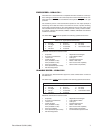
PARTS PICTOGRAPH **
*
*
* TO SEE THE MATING CONNECTOR FOR THE ITEM SHOWN, REFER TO FIGURE 12.
** For those who need AUX/ALARM interface capabilities, a kit is available (see Section 7.0 under Optional Accessories).
*** The items pictured above represent a typical shipment configuration for an LRD41 model. The above list is meant to be informative
and is not an exclusive grouping of items sent (additional minor hardware may also accompany a shipment).
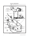
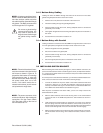
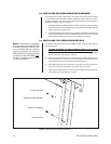
(See Figure 6)
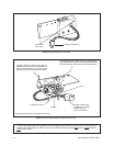
(See Figure 1)
1
1
0**