


Pelco Manual C557M (10/99) 3
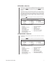
REVISION HISTORY
Manual # Date Comments
C557M 4/97 Original version.
5/98 Added certifications. Changed pagination.
5/99 Revised switch settings in Table C for addresses 24,
56, 88, 120, 152, 184, 216 and 248.
10/99 Revised Section 4.6 to include preset operation. Added
Section 4.9. Changes made per ECO 99-5334.
Changed value of F1 from 1A to 2A for LRD41C21-1
per ECO 99-5613.
LIST OF ILLUSTRATIONS
Figure Page
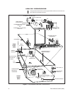
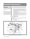
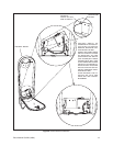
1 Fully Populated LRD41CXX-* Receiver/Driver ..................................8
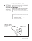
2 Mounting Receiver/Driver Box Into LWM41 Wall Mount ....................9
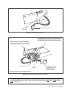
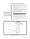
3 Arm Rear Entry Locations ................................................................ 10
4 Switch Bracket (Front View) ..............................................................12
5 Switch Bracket Power Terminal Connections ....................................12
6 Switch Bracket Installation ................................................................ 13
7 Receiver Box Mounting Hardware ....................................................14
8 Receiver/Driver Box Cable Connectors ............................................15
9 Assembly Layout for Receiver/Driver Board (PCB9000233 Shown) .17
10 Preposition Alarm Wiring ..................................................................18
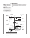
11 Sample Aux Function Wiring Diagram ..............................................18
12 Connector Wiring Pin-Outs ...............................................................19
13 37-pin Connector Wiring ...................................................................27
LIST OF TABLES
Table Page
A Voltage Settings ................................................................................17
B Address Switch Settings for SW *P-Type Control .............................21
C Address Switch Settings for SW *D-Type Control .............................22