


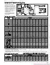

9
Prior to Operation
Although this unit has been assembled and fire-tested at the
factory, the following pre-operational procedures should be
performed to assure proper on-site operation:
1. Turn off all electric power to the unit.
2. Check burner to insure proper alignment.
3. Check fan clearance. Fan should not contact casing when
spun by hand.
4. Check all electrical connections to be sure they are secure.
5. If you are not familiar with the unit’s controls (i.e.
combination gas control), refer to the control manufacturer’s
literature supplied with the unit.
6. Check that all horizontal deflector blades are open a
minimum of 30° as measured from vertical.
L
ighting Instructions (also on unit)
For Units with Standing Pilot
1. Set thermostat to lowest setting. Move gas control knob (or
lever) to off and wait 5 minutes.
2. Move gas control knob to PILOT (or move gas control lever
to SET) and depress reset button while lighting the pilot and
hold for 1 minute after pilot is lit.
3. Move gas control knob (or lever) to ON.
4. Set thermostat to desired setting.
F
or Units with Intermittent Pilot
1. Set thermostat to lowest setting. Move gas control knob (or
lever) to off and wait 5 minutes.
2. Move gas control knob (or lever) to ON.
3. Set thermostat to desired setting (pilot and main burner will
light automatically when thermostat calls for heat).
S
hut Down Instructions
Turn off power and close manual gas valve.
A
fter Initial Start Up
1. Check pilot flame adjustment as discussed below.
2. Check gas piping for leaks with a soap bubble solution to
insure safe operation.
3. Check gas input rate to assure proper gas flow and
pressure.
P
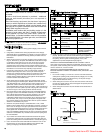
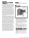
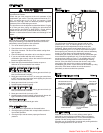
ilot Flame Adjustment
The pilot burner is orificed to burn properly with an inlet
pressure of 6-7" W.C. on natural gas and 12-14" W.C. on
propane gas, but final adjustment must be made after
installation. Adjust to have a soft steady flame 3/4" to 1" long
and encompassing 3/8"-1/2" of the tip of the thermocouple or
flame sensing rod. Normally this flame will produce satisfactory
results. To adjust flame use pilot adjustment screw on
combination gas control (for location, see the combination gas
control literature supplied with unit). If the pilot flame is longer
and larger than shown by Figure 7, it is possible that it may
cause soot and/or impinge on the heat exchanger causing
burnout. If the pilot flame is shorter than shown it may cause
poor ignition and result in the controls not opening the
combination gas control. A short flame can be caused by a dirty
pilot orifice. Pilot flame condition should be observed
periodically to assure trouble-free operation.
N
atural
Gas Flame Control
Control of burner flames on units utilizing natural gas is
achieved by moving the gas manifold to either increase or
decrease primary combustion air. Prior to flame adjustment,
operate unit with casing closed for about five minutes.
Operation can be viewed after loosening and pushing aside the
blue gas designation disc on rear of unit.
CAUTION
Start-up and adjustment procedures should be performed by
a qualified serviceman.
Check the gas inlet pressure at the unit upstream of the
combination gas control. The inlet pressure should be 6"-7"
W.C. on natural gas or 12"-14" W.C. on propane. If inlet
pressure is too high, install an additional pressure regulator
upstream of the combination gas control.
The pilot flame must be adjusted as described below. Purging
of air from gas lines, piping, and lighting the pilot should be
performed as described in ANSI Z223.1-latest edition
“National Fuel Gas Code” (CAN/CGA-B149 in Canada).
Be sure no obstructions block air intake and discharge of unit
heater.
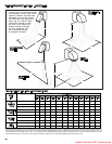
OPERATION
Figure 7
Correct Pilot Flame
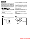
Figure 8
Typical combination gas control
GAS CONTROL KNOB
INLET
PRESSURE TAP
PRESSURE REGULATOR
ADJUSTMENT SCREW
(UNDER CAP SCREW)
ELECTRICAL
CONNECTION
TERMINALS
OUTLET
PRESSURE
TAP
OUTLET
PILOT TUBING
CONNECTION
PILOT ADJUSTMENT
SCREW
RESET BUTTON
INLET
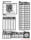
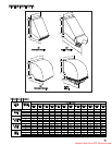
Heater Parts from ACF Greenhouses