


In the U.S., the installation of these units must comply with the “National
Fuel Gas Code,” ANSI Z223.1, latest edition (also known as NFPA 54)
and other applicable local building codes.
In Canada, the installation of these units must comply with local
plumbing or waste water codes and other applicable codes and with the
current code CAN/CGA-B149.1, “Installation Code for Natural Gas
Burning Appliances and Equipment” or CAN/CGA-B149.2, “Installation
Code for Propane Burning Appliances and Equipment.”
1. Alliinstallation and service of these units must be performed by a
qualified installation and service agency only as defined in ANSI
Z223.1, latest edition or in Canada by a licensed gas fitter.
2. This unit is certified by A.G.A. and by C.G.A., with the controls
furnished. For replacement parts, submit the complete model and
serial numbers shown on rating plate on the unit. Modine reserves
the right to substitute other authorized controls as replacements.
3. Unit is balanced for correct performance. Do not alter fan or operate
motors at reduced speed.
4. Information on controls is supplied separately.
5. Modine unit heaters use the same burner for natural and propane
gases.
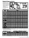
Locating Unit Heaters
In locating units, consider general space-heating requirements,
availability of gas, and proximity to vent locations. Unit heaters should
be located so heated air streams wipe exposed walls without blowing
directly against them. In multiple unit installations, arrange units so that
each supports the air stream from another, setting up circulatory air
movement in the area, but maintain separation between units so
discharge from one unit will not be directed into the inlet of another. In
buildings exposed to prevailing winds, a large portion of the heated air
should be directed along the windward wall. Avoid interference of air
streams as much as possible.
Mounting height (measured from bottom of unit) at which unit heaters
are installed is critical. Maximum mounting heights are listed in Table 7
on page 18. Alternate mounting heights for units with deflector hoods or
nozzles are shown on pages 14,16 and 17. The maximum mounting
height for any unit is that height above which the unit will not deliver
heated air to the floor.The maximum mounting heights must not be
exceeded in order to assure maximum comfort.
Modine unit heaters are designed for use in heating applications with
ambient temperatures between 32° F and 90° F. If an application exists
where ambient temperatures can be expected to fall outside of this
range, contact factory for recommendations.
Combustion Air Requirements
Units installed in tightly sealed buildings or confined spaces should be
provided with two permanent openings, one near the top of the
enclosure and one near the bottom. Each opening should have a free
area of not less than one square inch per 1,000 BTU per hour of the
total input rating of all units in the enclosure, freely communicating with
interior areas having, in turn, adequate infiltration from the outside.
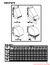
Unit Suspension
Be sure the means of suspension is adequate to support the weight of the
unit. (See page 12 for unit weights.) For proper operation, the unit must be
installed in a level horizontal position. Clearances to combustibles as
specified above must be strictly maintained. Do not install standard unit
heaters above the maximum mounting height shown in Table 7 on page
13, or below seven feet from the bottom of the unit to the floor.
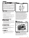
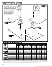
On all propeller units, except the PAE 300, PAE 350 and PAE 400, two
tapped holes (3/8-16) are located in the top of the unit to receive ceiling
hangers.
Units with two point suspension, models PAE30 through PAE250,
incorporate a level hanging feature. Depending on what options and
accessories are being used, the heater may not hang level as received
from the factory. Do not hang heaters with deflector hoods until referring
to the “installation manual for deflector hoods” and making the
recommended preliminary adjustments on the heater. These preliminary
adjustments need to be made with the heater resting on the floor.
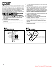
PAE30 through PAE250 units without deflector hoods that do not hang
level after being installed, can be corrected in place. Simply remove
both outer side panels (screws to remove are on back flange of side
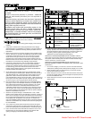
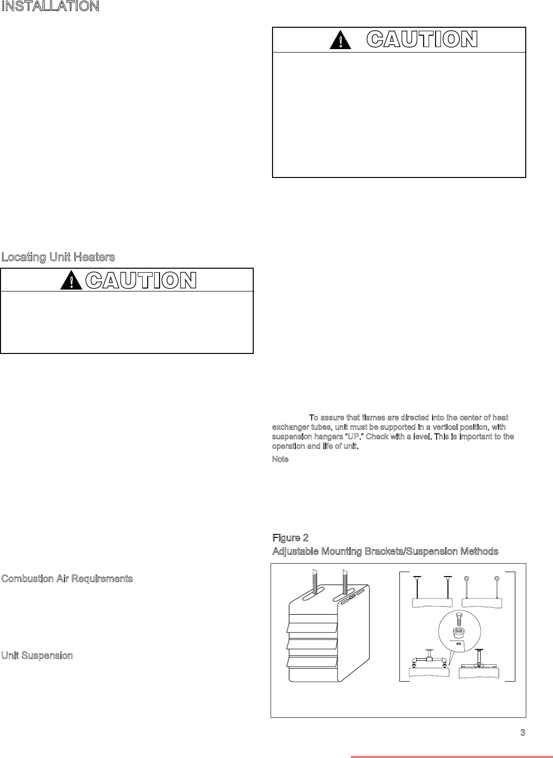
panel) and you will see the (adjustable) mounting brackets (Fig. 2).
Loosen the set screws holding the mounting brackets in place and using
a rubber mallet or something similar, tap the heater into a position
where it does hang level. Re-tighten set screws and replace the outer
side panels
The PAE 300, PAE 350 and PAE 400 have four mounting holes. On all
blower units, except the PAE 300, PAE 350 and PAE 400, two tapped
holes are provided in the top of the unit and two holes in the blower
support bracket. The PAE 300, PAE 350 and PAE 400 have four tapped
holes in the top of the unit and two in the blower support bracket for
mounting.
T
o assure that flames are directed into the center of heat
exchanger tubes, unit must be supported in a vertical position, with
suspension hangers “UP.” Check with a level. This is important to the
operation and life of unit.
Note
: Pipe hanger adapter kits, as shown in Figure 2, are available as
accessories from Modine. The hardware allows for pipe caps to be
secured into the top of the unit heater with machine screws (as
illustrated - machine screws are 3/8 - 16 x 1.75 UNC-2A THD). The pipe
caps can then accommodate 3/4" NPT pipe for mounting. Three
different kits are available with either 2, 4, or 6 adapters per kit. See
price sheet to determine proper kit.
3
INSTALLATION
CAUTION
Units must not be installed in potentially explosive, flammable
or corrosive atmosphere.
To prevent premature heat exchanger failure do not locate
ANY gas-fired unit in areas where chlorinated, halogenated
or acid vapors are present in the atmosphere.
!
CAUTION
For all sizes, minimum clearance to combustibles from the
bottom is 12" and from the sides 18"; for PAE sizes 30-100
from the top is 1" and from the vent connector 2"; for PAE
sizes 125-300 from the top is 2" and from the vent connector
3"; for PAE sizes 350 & 400 from the top is 3" and from the
vent connector 6”; and for all BAE sizes from the top and vent
connector is 6".
Allow at least 12" at the rear, or 6" beyond the end of the
motor (whichever is greater), to provide ample air for
combustion and for proper operation of fan. Provide
clearance for opening of the hinged bottom for servicing –
SEE FIGURE 1A.
!
Figure 2
Adjustable Mounting Brackets/Suspension Methods
REMOVE SIDE PANELS TO
ADJUST MOUNTING
BRACKETS
SUSPENSION WITH PIPE
ADAPTER KIT
Heater Parts from ACF Greenhouses